Content Menu
● Pressure and flow do different jobs
● Choose the shielding gas first
● Set TIG flow for coverage, not maximum output
>> Read the flowmeter under operating conditions
>> Use pre-flow and post-flow deliberately
● How to set up and verify the system
● Troubleshoot shielding without wasting gas
>> A practical shop-floor example
● What a TIG regulator buyer should specify
● Specify a regulator for the whole TIG setup
>> 1.What is the difference between a TIG regulator and a flowmeter?
>> 2.What argon flow rate should I use for TIG welding?
>> 3.Can too much shielding gas cause a bad TIG weld?
>> 4.Do I need a gas lens for TIG welding?
>> 5.Can I use an oxygen or CO₂ regulator on an argon cylinder?
>> 6.Is a dual-stage regulator necessary for TIG welding?
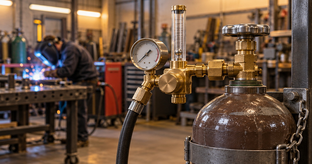
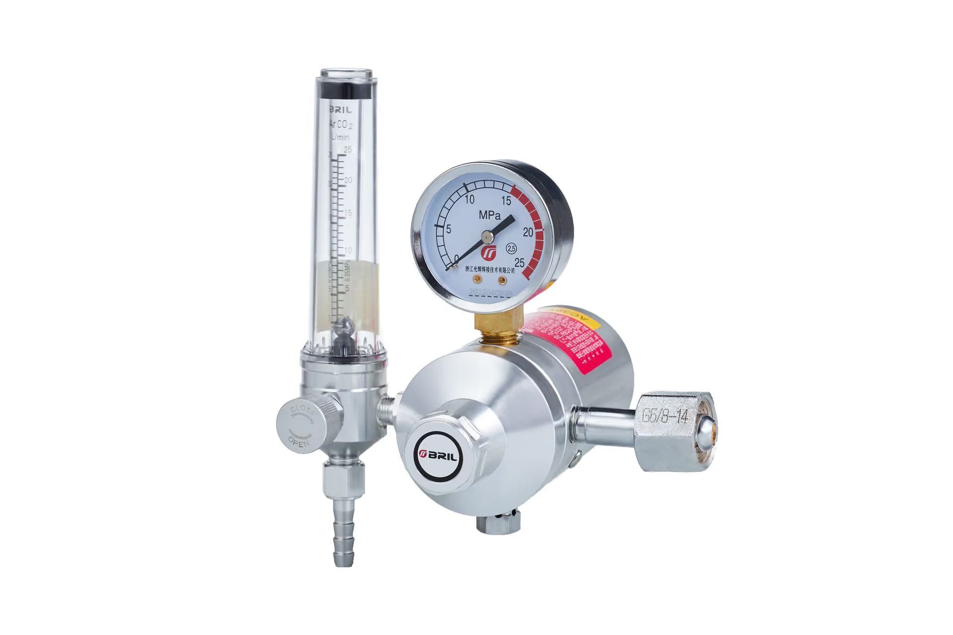
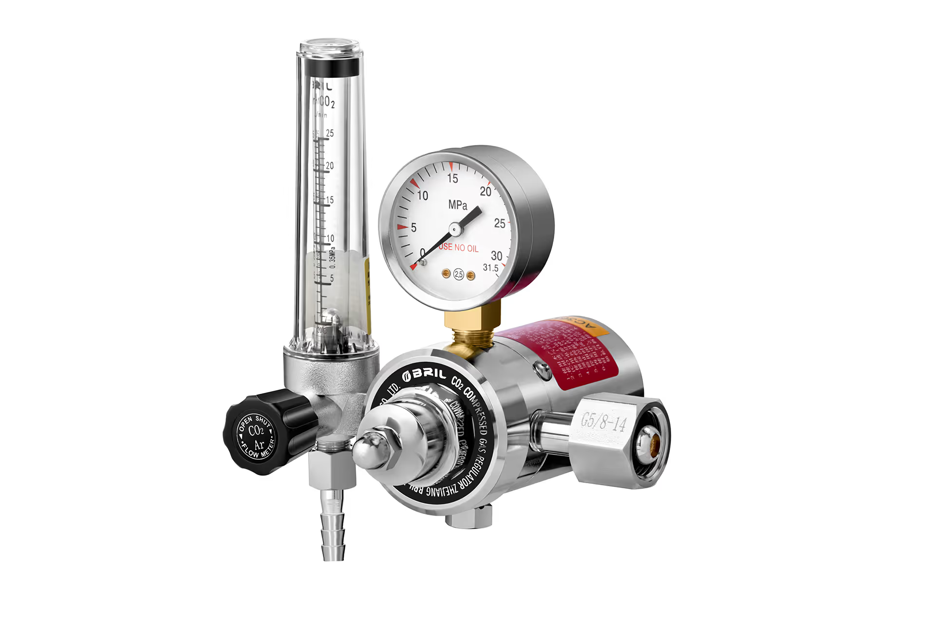
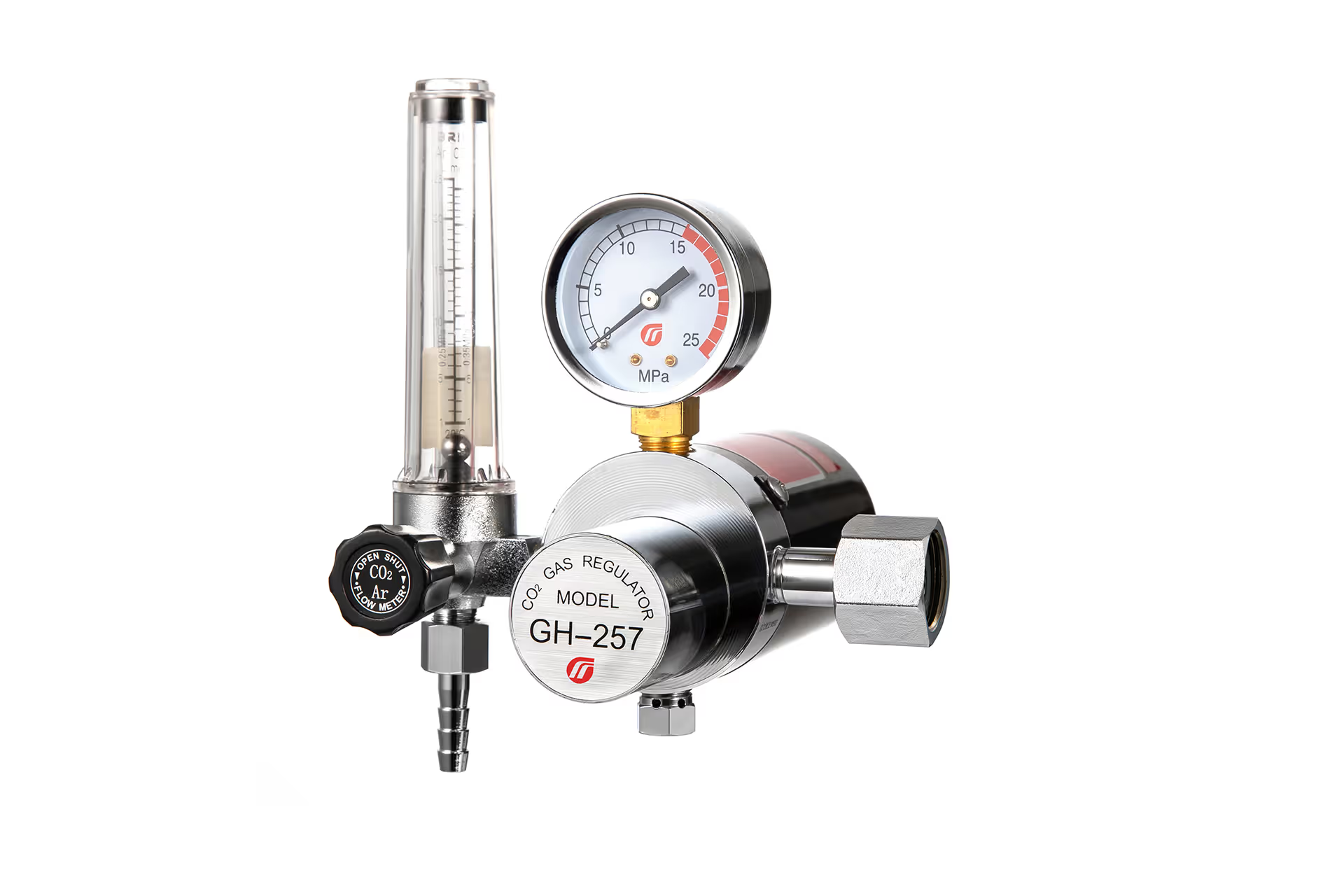
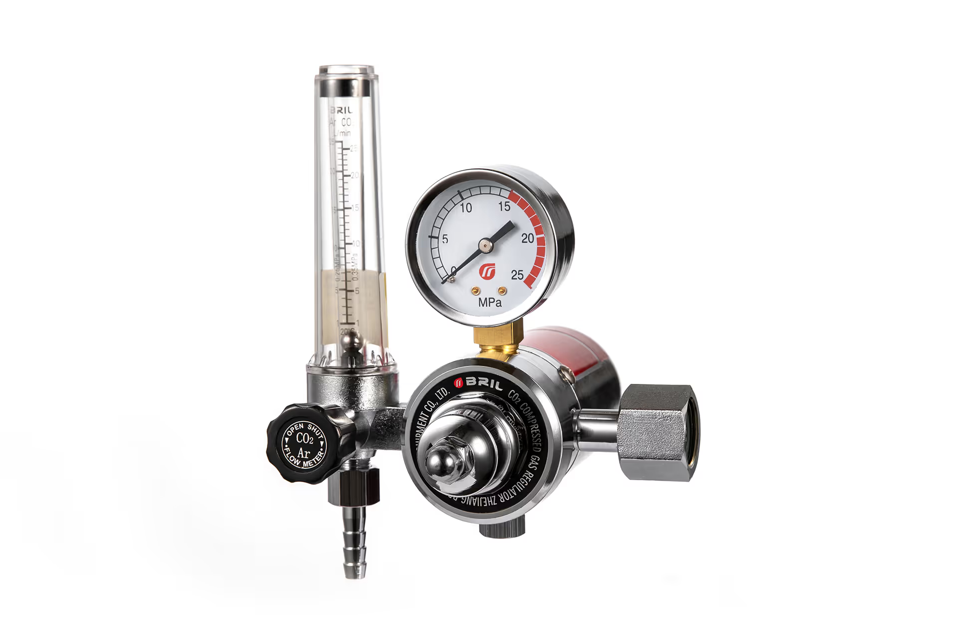
A welding gas regulator for TIG welding has two related jobs: reduce pressure from the gas supply and help deliver a stable, appropriate shielding-gas flow to the torch. Getting both right matters. Too little coverage can expose the molten weld and hot tungsten to air; simply turning the flow higher can create turbulence and make contamination worse. For most TIG applications, 100% argon is the starting shielding gas, and a regulator with a suitable flowmeter makes its delivery easier to set and monitor.
The correct setup is not one universal number on a gauge. Gas choice, cup design, hose condition, drafts, and the welding procedure all affect the result.
Pressure and flow do different jobs
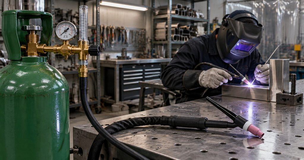
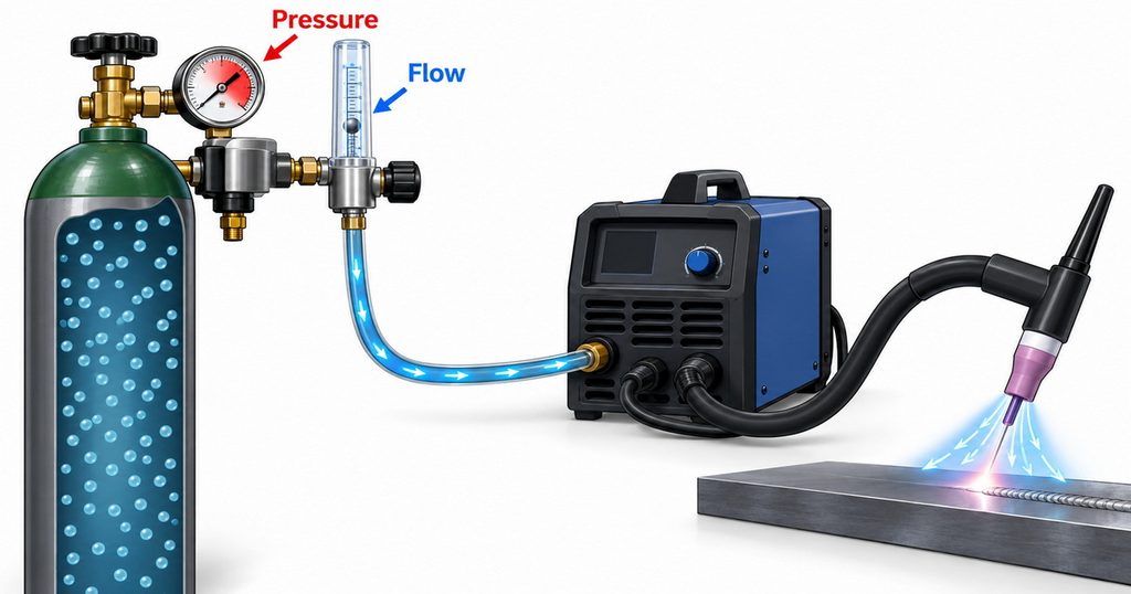
A regulator reduces the high pressure supplied by a cylinder to a usable delivery pressure. A flowmeter or flow-calibrated device indicates how much gas is being delivered, commonly in cubic feet per hour (CFH) or liters per minute. Cylinder pressure is not shielding-gas flow. A pressure gauge can tell you about the supply, but it cannot, by itself, confirm the flow reaching the weld. ISO 2503:2009 addresses both single- and two-stage cylinder regulators, including versions equipped with flow-metering devices for TIG and related welding processes.
Think of the gas path as one system: cylinder, regulator, flow-control device, hose, welder gas valve, torch, and cup. A sound regulator cannot compensate for a kinked hose, a leaking connection, a damaged torch component, or a draft across the workpiece. Lincoln Electric’s TIG troubleshooting guidance specifically points users toward gas supply, flow setting, hose restriction, and leaks when shielding is inadequate.
For a purchaser, this distinction affects the specification. “Stable outlet pressure” describes part of regulator performance. “Usable TIG shielding control” also requires an appropriate way to set and verify flow under the intended operating conditions.
Choose the shielding gas first
Miller identifies 100% argon as the best all-around TIG shielding gas. It offers reliable arc starting and stability across a broad range of materials. Helium can provide greater heat input, while argon–helium blends offer a compromise between heat and argon’s easier starting behavior. Gas selection should nevertheless follow any applicable welding procedure specification (WPS), not a general blog recommendation.
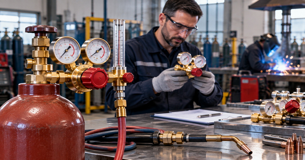
This is an important equipment boundary for buyers. A manufacturer may offer argon, CO₂, oxygen, acetylene, propane, nitrogen, and heated CO₂ regulators, but that does not make those products interchangeable. A standard argon TIG setup is not a reason to substitute an oxygen or fuel-gas regulator. OSHA states that pressure-reducing regulators must be used only for the gas and pressures for which they are intended.
Before ordering, confirm the exact gas or approved mixture, cylinder or manifold source, inlet connection, maximum inlet pressure, required outlet arrangement, and flowmeter calibration. Connection conventions vary by gas and market: CONCOA’s U.S. reference, for example, lists CGA-580 for argon and nitrogen, CGA-540 for oxygen, and CGA-320 for carbon dioxide. Confirm the connection on the *actual cylinder and in the destination market* rather than ordering from a generic product photograph.
Set TIG flow for coverage, not maximum output
Miller reports that TIG shielding-gas flow commonly falls between 10 and 35 CFH. That is a working range, not a prescribed setting for every cup, joint, or gas. Its central recommendation is to use the lowest effective flow that maintains shielding: insufficient flow leaves the weld exposed, while excessive flow can disturb the gas column and draw surrounding air into it.
| Setup factor | What it can change | Practical response |
|---|---|---|
| Cup diameter and shape | How the shielding gas leaves the torch and covers the joint | Choose a cup suited to the access and required coverage; verify it with the actual weld. |
| Gas lens or standard collet body | How uniformly gas travels through the cup | Consider a gas lens when coverage is critical or greater tungsten extension is needed. |
| Drafts and nearby airflow | Whether surrounding air disrupts the shield | Reduce the draft before increasing flow. |
| Hose length and condition | Gas behavior at startup and consistency of delivery | Inspect for damage or restriction; assess startup surges on long lines. |
| WPS requirements | Permitted gas, equipment, and operating settings | Follow the approved procedure when one applies. |
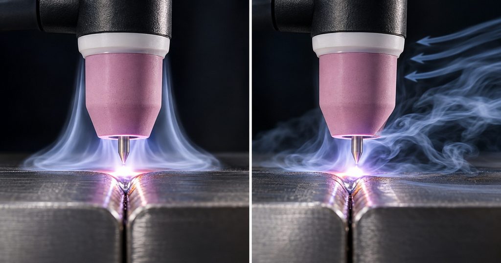
These factors explain why a copied CFH value can succeed on one bench and fail on another. Miller notes that gas lenses produce a more uniform flow than standard collet bodies and that long gas lines can cause a brief high-flow surge at arc start.
Read the flowmeter under operating conditions
Set the flow while shielding gas is actually passing through the system, using the machine’s gas-test or torch-control procedure as instructed by its manufacturer. A static reading does not establish the operating flow. Lincoln Electric’s TIG instructions, for example, direct the operator to activate gas flow before setting the flowmeter. Read the scale and indicator according to the specific flowmeter manufacturer’s instructions, and check that the meter is intended for the gas in use.
A flowmeter at the cylinder is also not a complete diagnosis of what happens at the cup. If the indicated flow looks reasonable but the weld still shows contamination, inspect the downstream gas path and torch assembly before changing the setting.
Use pre-flow and post-flow deliberately
Pre-flow establishes shielding before arc initiation. Post-flow protects the solidifying weld area and cooling tungsten after the arc stops. Miller recommends at least 0.2 seconds of pre-flow and a minimum eight seconds of post-flow, while also describing welding amperage divided by 10 as a post-flow starting rule. Treat those figures as guidance to check against the machine manual, tungsten condition, and applicable WPS—not as settings that override an approved procedure.
Keep the cup over the weld termination until post-flow ends. Pulling it away immediately defeats the protection you have just set. If a long line produces an obvious burst of gas at startup, Miller recommends considering a shorter line or more pre-flow time rather than assuming a higher steady-state CFH setting will solve the problem.
How to set up and verify the system
This checklist adds a practical step often missing from regulator articles: verify the complete gas path, not merely the regulator dial.
1. Confirm compatibility. Read the cylinder label and regulator markings. Verify the specified gas service, inlet connection, pressure rating, hose, and flow-control arrangement. Do not force mismatched fittings or assume that similarly shaped regulators are interchangeable.
2. Inspect before connection. Secure the cylinder and examine the regulator connection, gauges, hose, and torch components for damage. OSHA calls for inspection of regulator union nuts and connections for faulty seats that could leak.
3. Connect and open as instructed. Follow the cylinder supplier’s and equipment manufacturer’s procedures. Stand to one side when opening the cylinder valve, and use the equipment only for its approved service.
4. Check for leakage. Use an approved leak-detection method suitable for the gas and equipment; never use a flame. If a regulator leaks or shows abnormal behavior, remove it from service and arrange qualified inspection rather than attempting an improvised repair.
5. Activate gas flow and set the meter. With the welding system operating in its prescribed gas-test mode, set an initial value appropriate to the WPS or setup. If no procedure specifies one, use the equipment maker’s guidance and adjust within a reasonable TIG working range while observing shielding performance.
6. Make and inspect a test weld. Check the weld and tungsten for signs of inadequate shielding. If problems appear, investigate drafts, torch assembly, hose condition, and gas timing before increasing flow.
7. Shut down correctly. Close the cylinder valve when work is finished and follow the supplier’s procedure for releasing trapped gas before removing a regulator.
Troubleshoot shielding without wasting gas
Poor weld appearance does not automatically mean “turn up the regulator.” Use the symptom to narrow the possible cause, then change one variable at a time.
| What you observe | Checks to make first | Why it matters |
|---|---|---|
| Porosity or visible oxidation | Gas supply, leaks, drafts, cup coverage, and torch position | Air may be reaching the weld despite an indicated flow reading. |
| Tungsten contamination after stopping | Post-flow setting and whether the torch stays over the weld | The hot electrode still needs shielding as it cools. |
| Rough starts after changing a long hose | Startup surge and pre-flow setting | A brief surge can disturb coverage even if steady flow is acceptable. |
| Flowmeter indicates flow but coverage seems weak | Kinked hose, obstructed path, torch assembly, and fittings | A cylinder-end indication does not identify every downstream fault. |
| Higher flow makes results worse | Excessive flow, cup choice, and drafts | More gas can increase turbulence rather than improve protection. |
Miller describes both low-flow exposure and high-flow turbulence as contamination risks, while Lincoln Electric’s troubleshooting material identifies restricted hoses and gas-line leaks as possible causes of shielding trouble. Stop using equipment that appears to be leaking or malfunctioning; have it assessed by qualified personnel.
A practical shop-floor example
Suppose a TIG operator sees discoloration near the end of a weld. The flowmeter already shows a plausible setting. Raising flow may waste gas without fixing the defect. First, confirm that post-flow is active and that the torch remains over the weld while the metal and tungsten cool. Then inspect the cup, torch assembly, and nearby airflow. This is a diagnostic example, not a reported customer case or a claim about a particular product’s performance.
What a TIG regulator buyer should specify
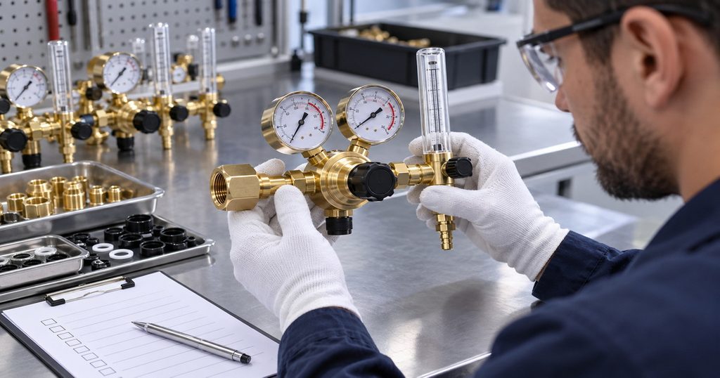
For an overseas brand, wholesaler, distributor, or equipment manufacturer, the purchase specification should cover more than body material and a photograph. Brass construction may be one selection criterion, but a buyer also needs documented gas compatibility, connection accuracy, pressure and flow performance, inspection methods, and traceability appropriate to the intended market and application. ISO 2503:2009 provides a relevant standards reference for applicable cylinder-mounted welding regulators with or without flow-metering devices; citing it is not the same as claiming that a specific supplier’s product has been certified or tested to it.
Ask prospective OEM or ODM suppliers to define:
– Gas and application: Argon or approved TIG blend, rather than a broad, unsupported “universal gas” claim.
– Supply and connection: Cylinder or manifold arrangement, destination-market inlet, outlet fitting, and pressure ratings.
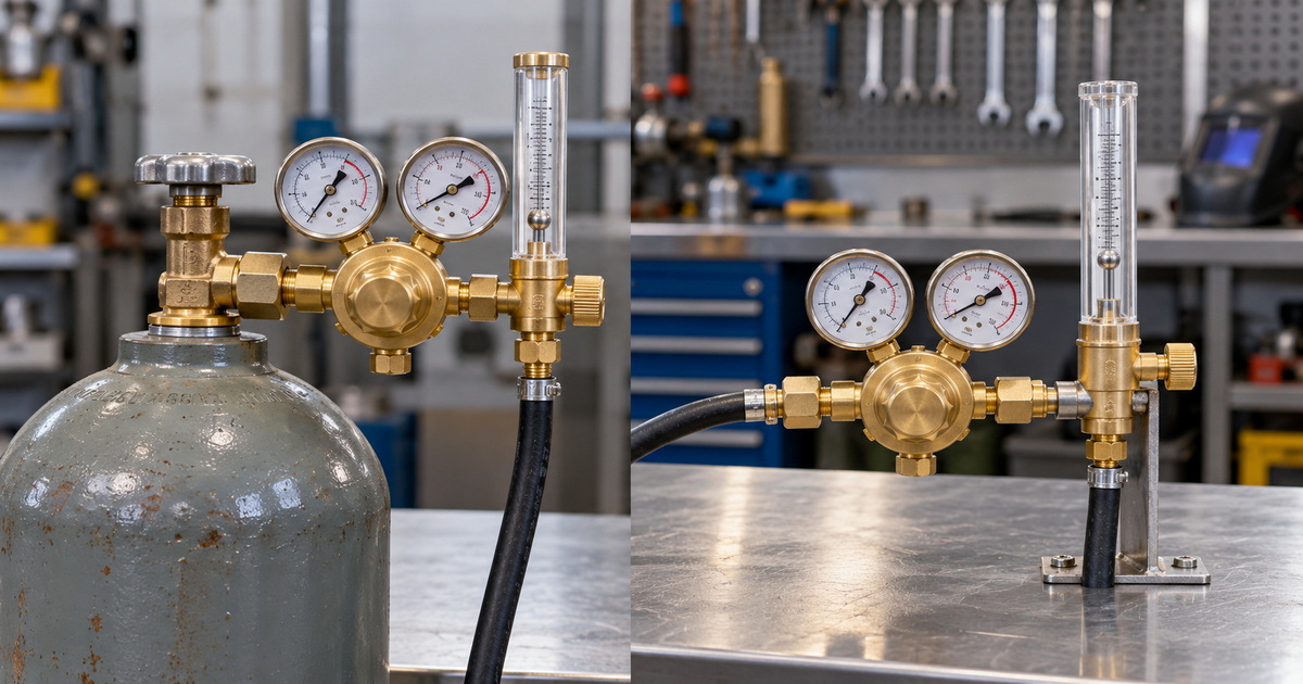
– Control format: Single-stage or dual-stage regulator, plus a compatible flowmeter or other specified flow-control device.
– Verification: Proposed pressure-control, leak, flow-indication, and final-inspection records for the exact model offered.
– Customization: Branding, gauge presentation, packaging, instructions, spare parts, and the process for approving design changes.
– Documentation: Applicable standard edition, test scope, material information, and evidence supporting any compliance claim.
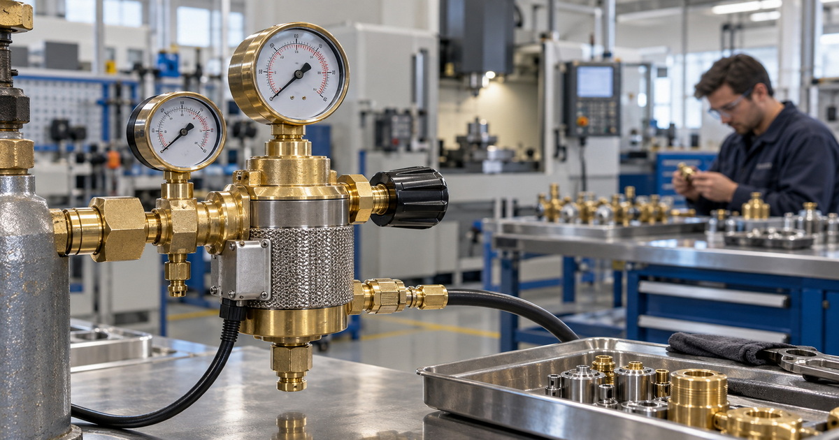
A dual-stage design can be worth evaluating where the purchaser needs tighter control as supply pressure changes, but its suitability must be established for the actual duty. Likewise, a CO₂ heated regulator may belong elsewhere in an industrial gas-control catalog; it should not be promoted as the default regulator for a conventional argon TIG setup. ISO 2503 covers relevant regulator categories, while the gas-specific selection still depends on the intended service.
Specify a regulator for the whole TIG setup
A dependable TIG gas supply starts with the right gas-specific regulator, but weld coverage is decided across the entire path to the torch. Select equipment that matches the cylinder and approved gas; set flow while gas is moving; verify the weld under real shop conditions; and diagnose leaks, drafts, cup geometry, and timing before increasing consumption. These checks connect pressure-control specifications to the outcome a welder needs: consistent shielding.
For an OEM or ODM quotation, send us your target market, gas or mixture, cylinder connection, inlet-pressure range, required flowmeter scale, outlet connection, intended TIG application, and any applicable WPS or compliance requirements. Our team can then discuss a customized regulator configuration and the inspection documentation required for your project. Do not publish product-specific performance or certification claims until the exact model’s evidence has been verified.
Frequently asked questions
1.What is the difference between a TIG regulator and a flowmeter?
The regulator reduces supply pressure; the flowmeter indicates gas flow. TIG buyers often choose an assembly that provides both functions so they can set shielding flow instead of relying on cylinder pressure alone. Check the product specification to confirm exactly what its gauges or scales measure.
2.What argon flow rate should I use for TIG welding?
Miller gives 10–35 CFH as a usual TIG range, but the correct value depends on consumables and surrounding conditions. Start with the WPS or equipment instructions, set flow while gas is moving, and use the lowest value that gives effective coverage on the actual job.
3.Can too much shielding gas cause a bad TIG weld?
Yes. Increasing flow can create turbulence that pulls surrounding air into the shielding stream. If coverage looks poor despite a reasonable setting, check for drafts, torch-assembly problems, and leaks before turning the flow higher.
4.Do I need a gas lens for TIG welding?
Not every job requires one. Miller describes a standard collet body as sufficient for some non-critical or practice work, while a gas lens helps create more uniform flow and can support greater tungsten extension when the application calls for it. Verify the setup against weld requirements and the WPS.
5.Can I use an oxygen or CO₂ regulator on an argon cylinder?
Do not assume so. Regulators must be intended for the gas and pressure in use, and cylinder connections differ. In CONCOA’s U.S. reference, argon, oxygen, and CO₂ have different listed CGA connections. Obtain a regulator approved for the actual gas, cylinder, and market.
6.Is a dual-stage regulator necessary for TIG welding?
Not automatically. ISO 2503 addresses both single- and two-stage regulators. Choose the design by the stability and operating requirements of your setup, and evaluate it together with the flow-control device rather than treating the number of stages as a substitute for a measured shielding flow.
References
1. Miller Electric, [“Best Practices for Proper Shielding Gas in TIG Welding”]. Source for gas selection, the 10–35 CFH usual range, gas lenses, turbulence, and pre-/post-flow guidance. [millerwelds]
2. Occupational Safety and Health Administration, [29 CFR 1910.253, “Oxygen-fuel gas welding and cutting”]. Source for gas-specific regulator use, connection inspection, cylinder-handling precautions, and repair requirements. Its scope is oxygen-fuel gas welding and cutting; it is cited for the relevant regulator and cylinder-safety provisions, not as a TIG flow-setting standard. [osha]
3. International Organization for Standardization, [ISO 2503:2009, “Gas welding equipment”]. Published scope for applicable single- and two-stage cylinder regulators, including flow-metering versions used in TIG. [iso]
4. CONCOA, [“CGA Fitting Reference”]. Examples of U.S. gas-specific cylinder connections; confirm the actual connection with the cylinder supplier. [concoa]
5. Lincoln Electric, [*Precision TIG 185 Operator’s Manual*]. Source for setting gas flow during operation and checking gas-line leaks or restrictions when troubleshooting shielding. [ch-delivery.lincolnelectric]
6. Lincoln Electric, [*Precision TIG 275 Operator’s Manual*]. Example of manufacturer instructions to activate gas flow before setting the flowmeter. [assets.lincolnelectric]
Hot Tags: TIG Welding Gas Regulator, Argon Regulator for TIG Welding, TIG Welding Regulator With Flowmeter, Argon Flowmeter Regulator, Industrial Argon Gas Regulator, Dual Stage Argon Regulator, Welding Gas Regulator Manufacturer, Argon Regulator Manufacturer, OEM TIG Welding Gas Regulator, Wholesale Argon Flowmeter Regulator