Content Menu
● Why Pressure and Flow Are Different
● Welding Gas Regulator Settings by Process
>> What Should a MIG Gas Regulator Be Set At?
>> What Should an Argon TIG Regulator Be Set At?
>> What Should Oxygen and Fuel Regulators Be Set At?
● How to Set a Welding Regulator Safely
● Diagnose Poor Shielding Before Increasing Flow
● Match the Regulator to the Gas
>> When Does a Heated CO₂ Regulator Help?
>> When Is a Dual-Stage Regulator Worth It?
● Safety Limits You Cannot Adjust Away
● Choose a Regulator Built for Your Application
>> 1.Should MIG shielding gas be set in PSI or CFH?
>> 2.What is a good argon setting for TIG welding?
>> 3.Can too much welding gas cause porosity?
>> 4.What pressure should I use for oxy-acetylene cutting?
>> 5.Can I use an argon regulator for CO₂ or oxygen?
>> 6.Why does my CO₂ regulator frost over?
>> 7.Is a dual-stage regulator the same as a dual-gauge regulator?
If you are asking, “What should my welding gas regulator be set at?”, first identify whether your equipment needs shielding-gas flow or torch delivery pressure. For short-circuit MIG welding, a documented starting point is 25–35 cubic feet per hour (CFH); aluminum TIG repair commonly starts at 15–20 CFH in the flat position. Oxy-fuel torches use pressure in pounds per square inch gauge (psig), and their settings come from the exact tip chart—not from a MIG flow-rate guide. These are starting points, not universal prescriptions.
Set MIG or TIG shielding gas while gas is actually flowing; set oxygen and fuel-gas delivery pressures using the torch and tip manufacturer’s instructions. Keep acetylene below the applicable 15-psig use limit. Never assume that a cylinder-pressure gauge tells you the flow reaching the weld.
Why Pressure and Flow Are Different
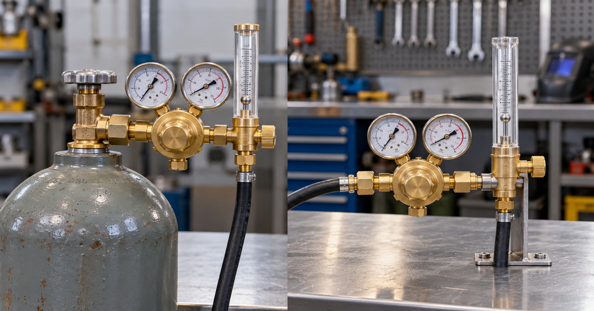
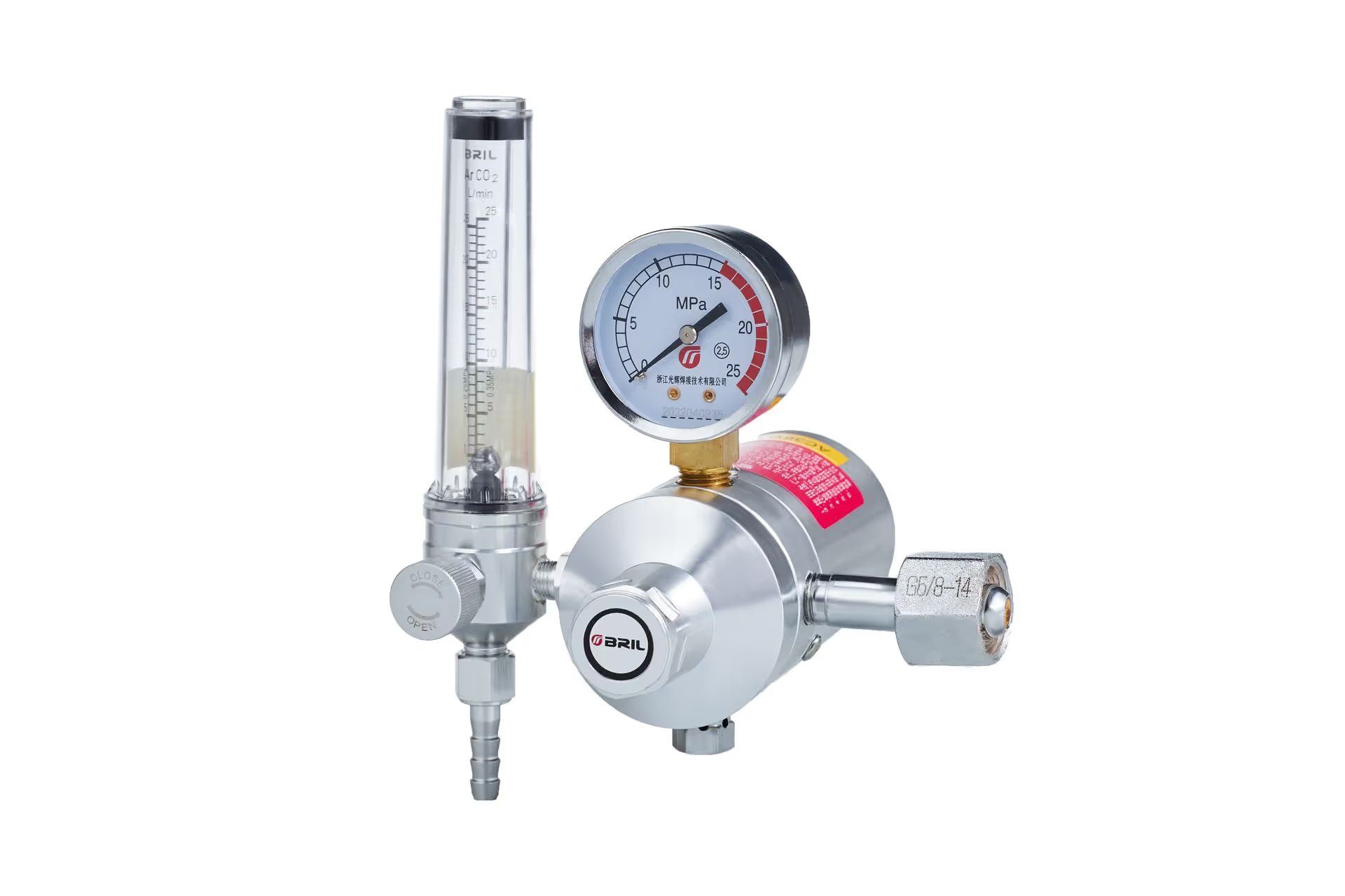
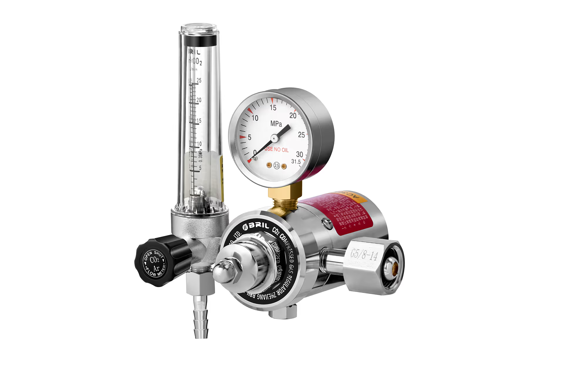
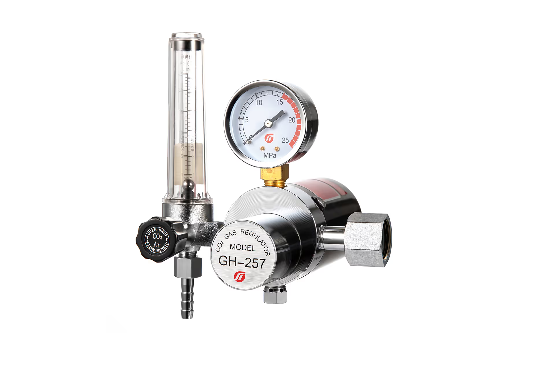
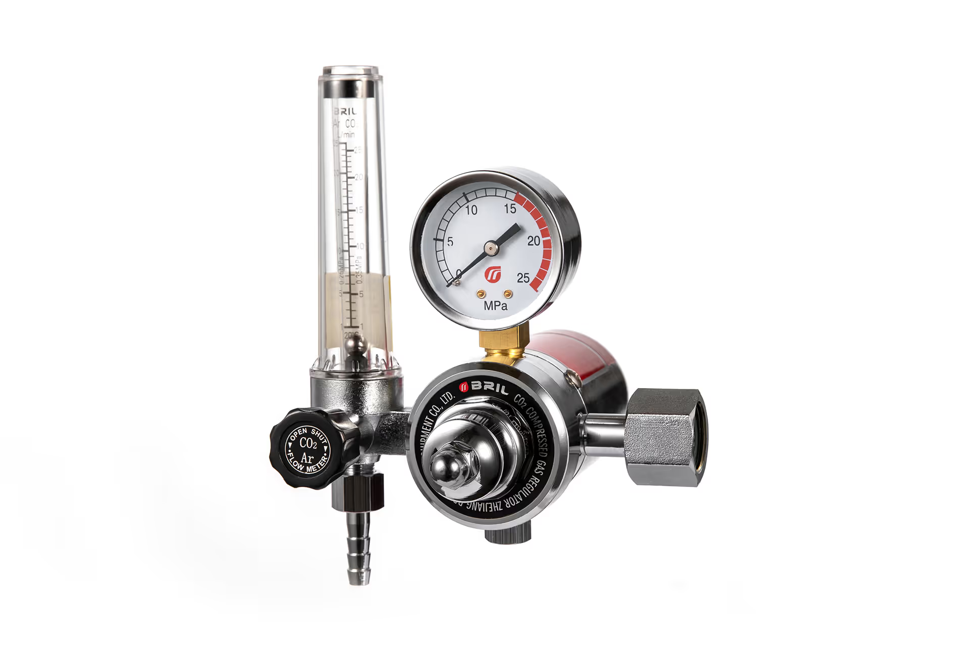
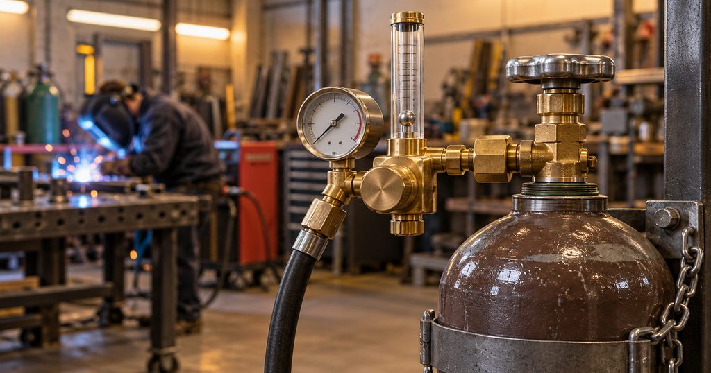
A regulator reduces cylinder pressure to a usable downstream pressure. A flowmeter or properly calibrated flowgauge indicates delivery rate. CFH and L/min describe gas volume per time; psig describes pressure. The high-pressure gauge shows the supply side, not the shielding-gas rate at your nozzle. A plain pressure regulator does not measure flow unless it includes a purpose-designed flow device.
That distinction matters because gas-shielded arc welding and oxy-fuel work solve different problems. MIG and TIG need enough shielding gas to cover the molten pool without creating excessive turbulence. Oxy-acetylene and oxy-propane cutting need appropriate oxygen and fuel-gas pressures for a particular torch and tip. A reading of “30” could mean 30 CFH, 30 L/min, or 30 psig—three very different instructions. Check the units and the device scale before turning the adjustment knob.
A flowgauge can estimate flow based on its design and calibration, while a flowmeter displays flow through a calibrated tube. Neither reading automatically confirms what emerges from a blocked nozzle or a leaking hose. When shielding quality is doubtful, check the gas at the gun or torch outlet with an appropriate external flow checker. Miller specifically recommends this as a troubleshooting step for MIG gas-coverage problems.
Welding Gas Regulator Settings by Process
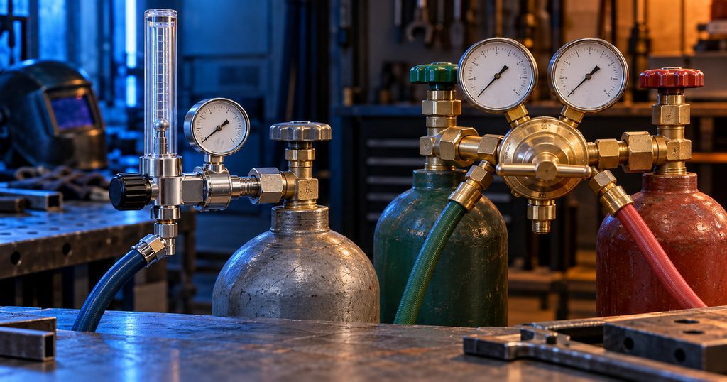
Use the table as a starting-point guide, then follow the equipment, filler-metal, procedure, and tip instructions that apply to your job. The quoted values below come from named manufacturer guidance; they do not establish one setting for every material or machine.
| Application | Documented starting point | What to verify |
|---|---|---|
| Short-circuit MIG with suitable shielding gas | 25–35 CFH, per Miller’s general short-circuit MIG guidance. | Gas mix, wire instructions, nozzle, draft protection, and measured flow while the gun is triggered. |
| Flat-position aluminum TIG repair with argon | 15–20 CFH, per Miller’s repair guidance. | Torch cup, joint position, gas coverage, and the machine’s post-flow settings. |
| Out-of-position or draft-affected aluminum TIG repair | 20–25 CFH in Miller’s stated repair example. | Shield the work from drafts rather than assuming more gas alone will solve them. |
| Oxy-acetylene cutting, Smith SC12-0 tip on 1/4-inch material | 30 psig oxygen and 10 psig acetylene in Miller’s specific SC-series tip chart. | Exact torch/tip combination and the chart’s required supply capacity. |
| Oxy-propane cutting, Smith SC40-0 tip on 1/4-inch material | 30 psig oxygen and 10 psig propane/natural gas in that specific chart. | Correct propane-rated regulator, hose, torch, and tip; do not copy this setting to other models. |
Conversion note: 1 CFH is approximately 0.47 L/min. Therefore, 25–35 CFH is about 12–17 L/min. Read the marked gas scale and units on your instrument rather than treating the two printed numbers as interchangeable.
What Should a MIG Gas Regulator Be Set At?
For short-circuit MIG, begin with the applicable manufacturer’s guidance—Miller gives 25–35 CFH—and set the flow with the gun triggered or the machine’s gas-test function active. Miller notes that low flow can cause porosity, while excessive flow can waste gas and create turbulence that also contributes to porosity. Different transfer modes may call for more flow; check the wire and machine documentation before changing the target.
The shielding gas matters as much as the number. Miller identifies 75% argon/25% CO₂ as a common mild-steel MIG blend and 100% CO₂ as a cost-conscious alternative with potentially more spatter. It recommends pure argon for many aluminum MIG applications and cautions against CO₂-containing gas for aluminum. Select the gas for the metal and transfer mode first; then set its flow on equipment calibrated for that gas.
If the weld still shows pores, avoid immediately turning the flow up. Check for an empty or incorrectly connected cylinder, a gas leak, a poorly seated gun, spatter in the nozzle, excessive contact-tip-to-work distance, or a draft. Miller describes all of these as relevant gas-coverage checks.
What Should an Argon TIG Regulator Be Set At?
For the documented aluminum repair example, start at 15–20 CFH on flat work and consider 20–25 CFH for out-of-position work or draft-affected conditions, as Miller advises. These are not blanket values for every TIG cup, gas lens, material, or torch. Choose a setting that produces adequate coverage without a noisy, turbulent stream, and protect the work area from air movement where practical.
Also check the TIG machine’s pre-flow and post-flow controls. Post-flow protects the hot tungsten and weld as they cool; it is a separate timing adjustment, not a higher CFH target. If a weld oxidizes at its end, investigate the shielding duration and technique as well as the regulator.
What Should Oxygen and Fuel Regulators Be Set At?
There is no single oxygen, acetylene, or propane pressure that applies to all welding, heating, and cutting tips. Match the torch, fuel, tip model, and material thickness to the manufacturer’s chart. For example, Miller’s Smith SC12-0 acetylene cutting tip lists 30 psig oxygen and 10 psig acetylene for 1/4-inch material; its SC40-0 propane/natural-gas cutting tip lists 30 psig oxygen and 10 psig fuel for the same stated thickness. Those chart entries are examples, not cross-brand defaults.
Set pressures in the manner prescribed by the torch manufacturer, including any requirement to adjust with gas flowing. Check that the regulator and hoses can deliver the needed rate under load. Acetylene must not be used above 15 psig under OSHA’s general-industry oxy-fuel rule. Use only regulators intended for the particular gas and pressure range; oxygen equipment must stay free of oil and grease.
How to Set a Welding Regulator Safely
The sequence below is a general checklist, not a substitute for the equipment manual or trained supervision. Oxy-fuel systems need their own torch-specific setup, purge, backflow protection, and lighting procedure. OSHA requires pressure-reducing regulators to be used only for their intended gas and pressure.
1. Confirm the gas and connection. Read the cylinder label, identify the process, and match the regulator inlet, outlet, pressure rating, and flow instrument to the gas. Never force a fitting or improvise an adapter to defeat gas-specific connections.
2. Secure and inspect the system. Keep cylinders stable; examine regulator connections, gauges, hoses, and torch parts for damage. Keep oxygen components free of oil and grease. Follow the applicable manufacturer instructions for inspecting the cylinder-valve outlet.
3. Back out the regulator adjustment. Start with downstream controls in the position specified by the equipment manual. Stand to the side of the regulator when opening the cylinder valve slowly.
4. Pressurize and check for leaks. Use a compatible, oxygen-safe leak-detection product where appropriate; never use a flame. If a connection continues to leak, isolate the supply and remove the faulty equipment from service.
5. Set the value under the right condition. For MIG/TIG, flow gas and adjust to the correct CFH or L/min reading. For oxy-fuel, follow the exact tip chart and the torch manufacturer’s pressure-setting and separate-gas purge instructions.
6. Make a controlled test and shut down correctly. Verify shielding or flame behavior on a suitable test piece. When finished, close cylinder valves and depressurize as the equipment instructions require before removing a regulator.
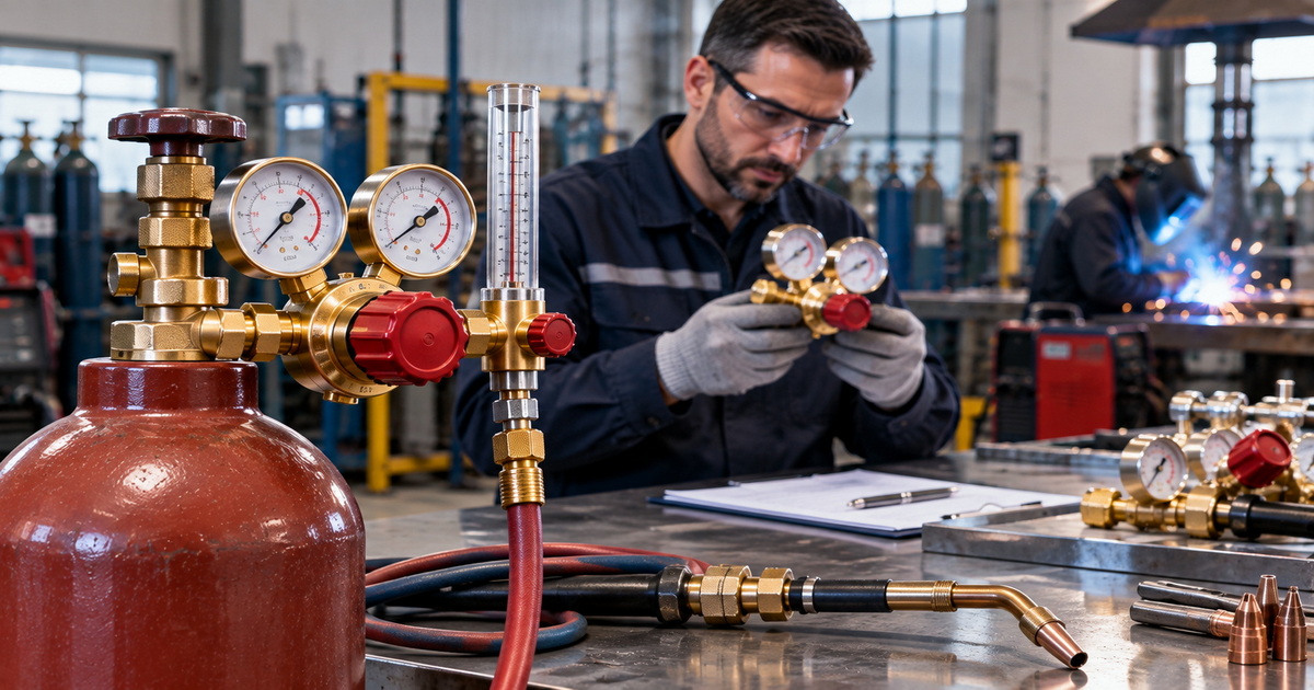
For oxy-fuel work, a reverse-flow check valve and a flashback arrestor do different jobs: the check valve limits reverse gas flow, while the arrestor is designed to stop an upstream flame. Select and place protective devices as specified for the system. A pressure setting is never a replacement for them.
Diagnose Poor Shielding Before Increasing Flow
When porosity appears, more gas feels like an easy fix. It can be the wrong fix. Too little shielding leaves the molten pool exposed; too much can generate turbulence and draw surrounding air into the weld area. The goal is effective coverage at the weld, not the largest number on the dial.
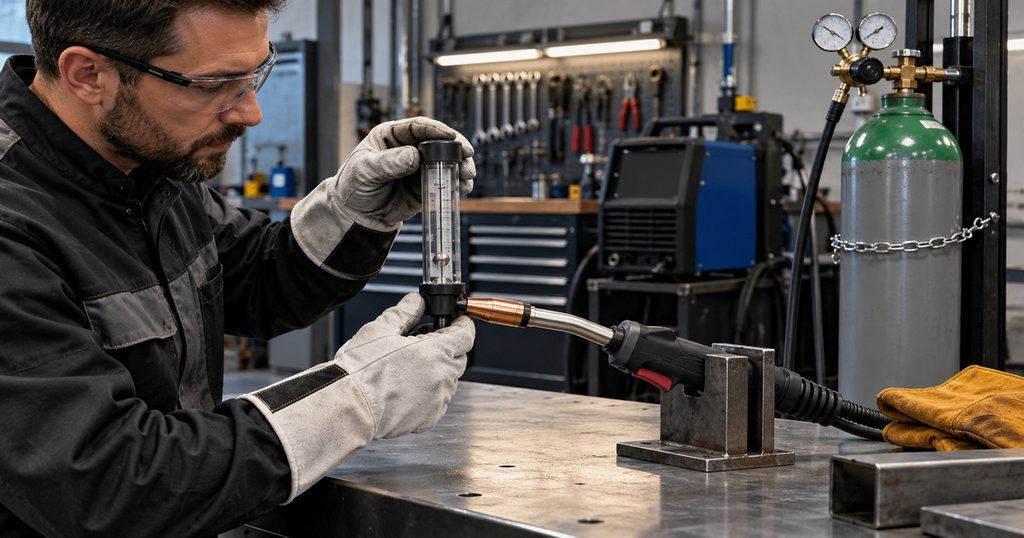
Use this short diagnostic sequence:
1. Check that the chosen gas and machine port match the welding process. A multiprocess machine may have separate TIG and MIG gas ports.
2. Trigger the gun or open the gas-test function. Confirm that the indicated flow is within the job’s documented range while gas is flowing.
3. Inspect fittings and hose for leaks, then examine the gun connection, diffuser, and nozzle for poor seating or spatter buildup.
4. Reduce drafts with a suitable wind block; check torch position and contact-tip-to-work distance.
5. If uncertainty remains, compare the regulator reading with an appropriate external flow checker at the gun outlet. If outlet flow is low, investigate restriction or leakage before raising the setting.
Match the Regulator to the Gas
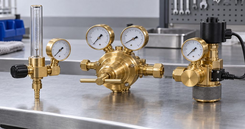
The setting is only useful if the hardware is appropriate. For brand owners, distributors, and welding-equipment manufacturers, specifying the regulator starts with gas service, inlet connection, rated pressure, required flow, measurement format, and applicable market requirements—not merely the appearance of a brass body. OSHA requires pressure-reducing regulators to be used only for their intended gases and pressures.
| Regulator application | Selection question | Why it matters |
|---|---|---|
| Argon or argon/CO₂ shielding gas | Does the assembly include a suitable flowmeter or calibrated flowgauge for the intended gas and delivery range? | Pressure control alone does not establish measured shielding-gas flow. |
| CO₂ shielding gas | Is the cylinder a standard gaseous-withdrawal type, and is sustained flow within the regulator’s rated capacity? | A named ESAB CO₂ flowmeter is specified for standard, non-siphoned cylinders; confirm your own cylinder and product configuration. |
| Heated CO₂ service | Does the verified duty cycle justify heating, and is the electrical configuration approved for the target market? | A documented Harris heated model is designed to resist freeze-up at higher CO₂ withdrawal rates; this does not mean every CO₂ job needs a heater. |
| Oxygen, acetylene, or propane | Is each regulator expressly approved for its gas, pressure, connection, and torch demand? | Fuel and oxygen equipment are not interchangeable; oxygen service requires strict cleanliness. |
| Dual-stage regulation | Is stable downstream pressure important as cylinder supply pressure changes? | Two-stage designs reduce pressure in two steps and are suited to applications requiring more consistent delivery. |
| Nitrogen or other industrial service | What are the actual inlet pressure, desired outlet pressure, flow, connection, and application? | Specify the gas and operating envelope rather than borrowing a MIG or oxy-fuel setting. |
When Does a Heated CO₂ Regulator Help?
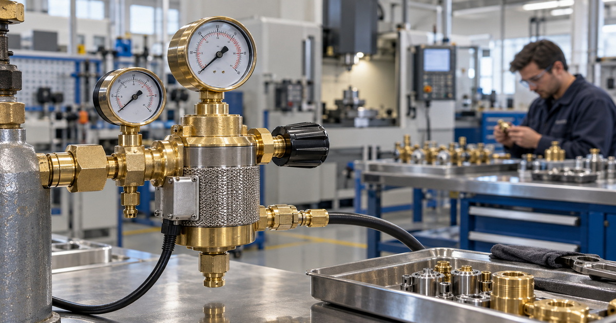
CO₂ withdrawal can cool equipment, and demanding applications may call for a purpose-built heated assembly. One Airgas-listed Harris model is rated for gaseous withdrawal from CO₂ cylinders up to 100 standard cubic feet per hour and includes a 200-watt heater; the listing explicitly describes resistance to high-flow regulator freeze-up. Those figures describe that model only, not the products offered on this page.
Before specifying a heater, determine the actual sustained flow, cylinder type, ambient conditions, power supply, and required certifications. A heater does not make an incorrectly sized cylinder, unsuitable regulator, or liquid-withdrawal arrangement safe. Publish your own verified maximum flow, heating power, voltage, temperature controls, and test results if you sell heated CO₂ regulators.
When Is a Dual-Stage Regulator Worth It?
A dual-stage regulator reduces pressure in two steps, helping stabilize delivery where pressure consistency matters. ESAB identifies high-precision welding among the uses for two-stage regulation. This is a pressure-control choice; it is not automatically a flowmeter. Buyers should still specify the flow-measurement device separately when shielding-gas flow must be read in CFH or L/min.
For OEM or ODM programs, ask suppliers for drawings and controlled specifications covering inlet/outlet fittings, inlet and delivery ranges, diaphragm and seal materials, applicable cleaning procedures, flow capacity, pressure stability, gauge readability, leakage testing, and traceability. These are procurement questions, not claims that any particular manufacturer’s product has passed a named certification.
Safety Limits You Cannot Adjust Away
A correct dial setting does not make an unsuitable gas system safe. In the United States, OSHA’s general-industry oxy-fuel rule limits acetylene utilization to 15 psig and requires regulators to match their intended gases and pressures. It also calls for oxygen equipment to be kept free of oily or greasy substances. Check the rules and standards applicable to your location and industry; OSHA is a U.S. reference, not a blanket statement of worldwide compliance.
Gas-shielded processes also need suitable ventilation. Argon and nitrogen can displace breathable air, and OSHA addresses ventilation and oxygen-deficiency hazards for welding and cutting in confined spaces. Do not use an increased shielding-gas setting as a workaround for unsafe ventilation.
For commercial buyers: Ask for application-specific documentation rather than a generic “international standards” promise. If a product is advertised as conforming to a particular standard or carrying a certification, show the exact standard, product scope, issuing body, and valid supporting records on the final page.
Choose a Regulator Built for Your Application
The best answer to “What should my welding gas regulator be set at?” starts with the process: measure flow for MIG/TIG shielding, but set pressure for oxy-fuel according to the exact torch-tip instructions. Use the documented ranges here only as starting points, check actual gas delivery, and select equipment expressly designed for the gas and job.
Need an OEM or ODM gas-control solution? Send our team your gas type, cylinder connection and destination market, inlet and outlet pressure ranges, target flow, duty cycle, preferred single- or dual-stage design, and any CO₂ heating requirement. Request the applicable drawings, material specifications, inspection plan, and verified compliance documents before approving a sample or production order.
Welding Gas Regulator FAQs
1.Should MIG shielding gas be set in PSI or CFH?
For routine MIG shielding setup, read the gas-flow scale in CFH or L/min, not cylinder pressure in psig. Miller’s short-circuit MIG starting point is 25–35 CFH; the correct value can change with the process and equipment. A pressure regulator without a calibrated flow device cannot tell you the shielding-gas flow.
2.What is a good argon setting for TIG welding?
For the specific aluminum TIG repair conditions described by Miller, begin at 15–20 CFH in the flat position; Miller suggests 20–25 CFH for out-of-position or draft-affected work. Other cup sizes, gas lenses, and procedures can require different settings.
3.Can too much welding gas cause porosity?
Yes. Miller explains that excessive shielding-gas flow can create turbulence and pull atmospheric contamination into the weld. Inspect drafts, leaks, and nozzle condition before assuming the solution is a higher setting.
4.What pressure should I use for oxy-acetylene cutting?
Use the exact manufacturer’s chart for your torch, tip, and thickness. As one limited example, Miller lists 30 psig oxygen and 10 psig acetylene for an SC12-0 tip cutting 1/4-inch material. OSHA’s general-industry limit prohibits acetylene utilization above 15 psig.
5.Can I use an argon regulator for CO₂ or oxygen?
Do not assume so. Confirm that the specific regulator assembly is approved for the intended gas, inlet connection, pressure range, and flow. OSHA requires regulators to be used only for their intended gas and pressure; oxygen service has additional cleanliness requirements.
6.Why does my CO₂ regulator frost over?
High CO₂ withdrawal can cool the assembly enough to create freeze-up problems. A purpose-built heated CO₂ regulator may help in a verified high-flow application: one Harris model is explicitly marketed to resist high-flow freeze-up. Check the cylinder configuration, flow demand, and product rating rather than applying external heat or assuming every frosted regulator needs the same fix.
7.Is a dual-stage regulator the same as a dual-gauge regulator?
No. Dual-stage describes two pressure-reduction stages. Two gauges simply show two readings, often supply and delivery pressure; their presence does not establish two-stage construction or indicate a built-in flowmeter. Check the model’s internal design and instrument specifications.
References
1. Miller Electric, [“What Type of Gas Is Best for MIG Welding in DIY Applications?”]. Source for short-circuit MIG flow, gas selection, porosity, and outlet-flow troubleshooting. [web:17]
2. Miller Electric, [“How to TIG Weld Aluminum for Repair.”]. Source for aluminum TIG flow ranges and post-flow context. [web:19]
3. U.S. Occupational Safety and Health Administration, [29 CFR 1910.253, “Oxygen-fuel gas welding and cutting.”]. Source for acetylene limit, regulator selection, cylinder/oxygen precautions, and equipment requirements. [web:31]
4. Miller Electric/Smith Equipment, [“Cutting and Gouging Tips,” issued March 2026 (PDF).] Source for the model-specific SC12-0 and SC40-0 oxy-fuel chart examples. [web:51]
5. Miller Electric, [“10 Steps for Safe Oxy-Fuel Torch Setup.”]. Source for setup sequence, leak testing, and distinction between check valves and flashback arrestors. [web:55]
6. Virginia Tech Environmental Health and Safety, [“Compressed Gas Cylinders.”] Source for regulator-versus-flowmeter distinction, compatible connections, and inert-gas precautions. [web:6]
7. ESAB University, [“Single Stage vs. Two Stage Regulators.”] Source for the pressure-stability comparison. [web:33]
8. Airgas, [Harris Model 715-100-SCFH heated CO₂ regulator listing.] Source for the example product’s 100-SCFH and 200-watt specifications; not a specification for our products. [web:36]
9. ESAB, [SR 310 Series Flow Meter.] Source for the standard non-siphoned CO₂ cylinder-use note. [web:35]
10. U.S. Occupational Safety and Health Administration, [29 CFR 1910.252, “General requirements.”] Source for welding ventilation and confined-space context. [web:46]
Hot Tags: Welding Gas Regulator Manufacturer, Welding Gas Regulator Supplier, CO₂ Regulator Manufacturer, Heated CO₂ Regulator Supplier, Argon Flowmeter Regulator Wholesale, MIG Welding Gas Regulator, TIG Welding Gas Regulator, Oxygen Regulator Manufacturer, Oxy Fuel Regulator Supplier, Dual Stage Gas Regulator OEM