Content Menu
>> What is an argon flow meter?
● Argon Flow Meter vs Rotameter: Key Differences
● Which Controls Shielding Gas More Precisely?
>> Pressure stability comes before fine adjustment
>> Gas and scale matching affect the reading
>> A readable number is not torch coverage
● A Practical Selection Test for Buyers
>> First, map the complete gas path
>> Next, define the working flow range
>> Finally, compare evidence—not adjectives
● Field Insight: Check the Torch, Not Just the Tube
● Three Errors That Distort Comparisons
>> Mistaking a flow setting for weld quality
>> Ignoring installation orientation
>> Treating safety as a connector detail
● When Each Option Makes Sense
>> 1.Is an argon flow meter the same as a rotameter?
>> 2.Do I need a regulator with a standalone rotameter?
>> 3.Can I use an argon scale for argon/CO₂?
>> 4.Does a higher CFH setting always improve TIG shielding?
>> 5.Why does the weld show porosity when the meter looks correct?
>> 6.Can a rotameter be installed horizontally?
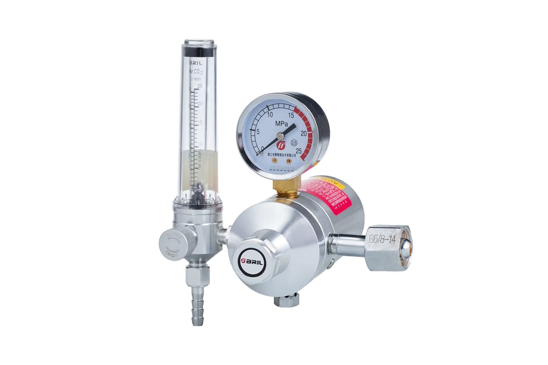
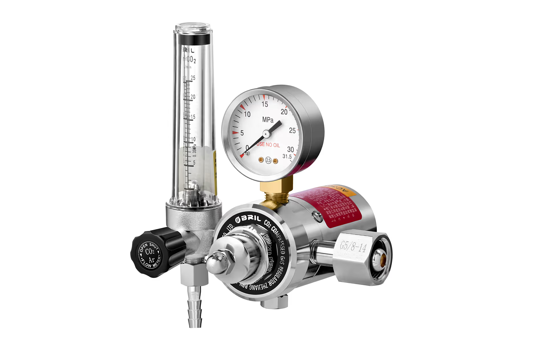
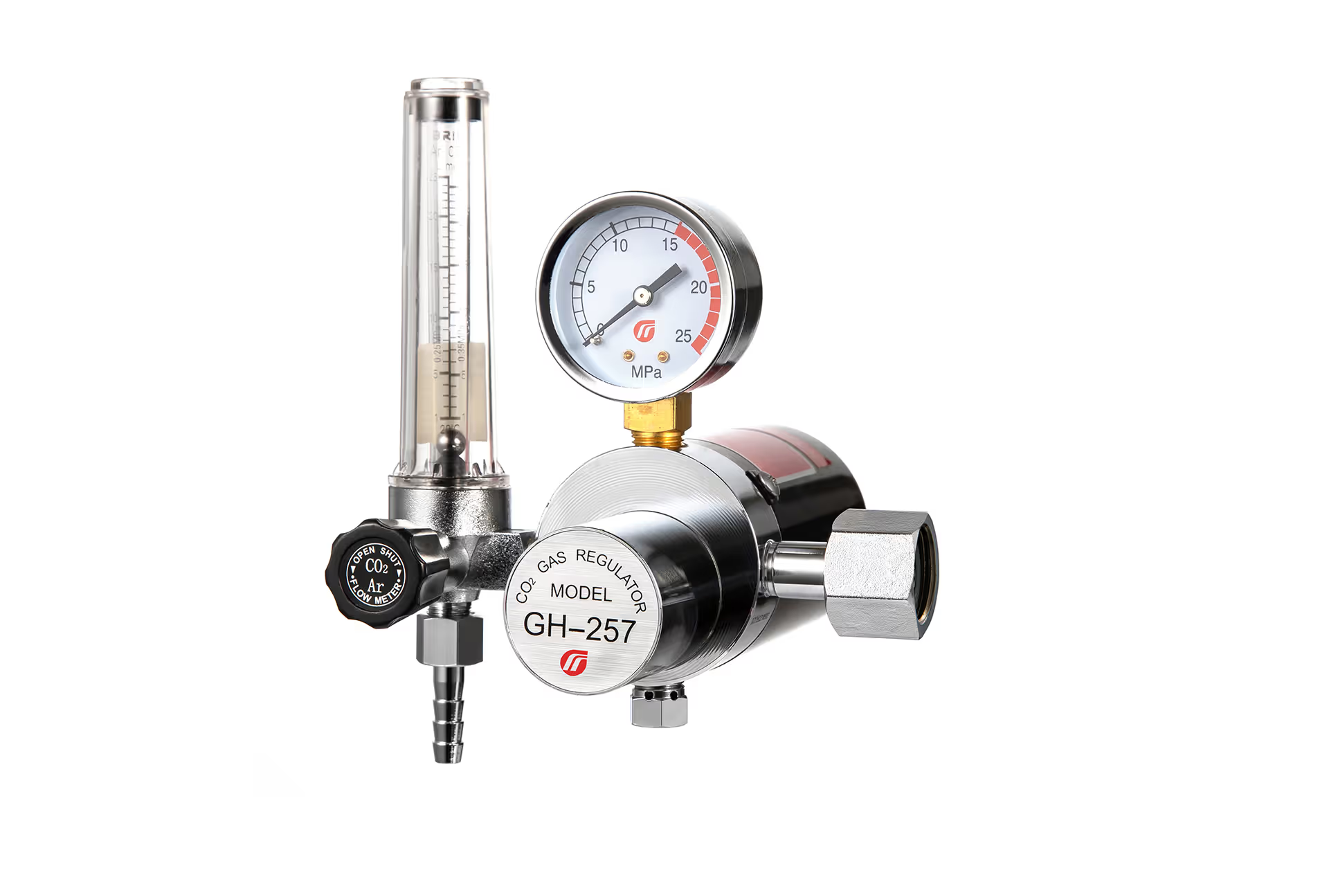
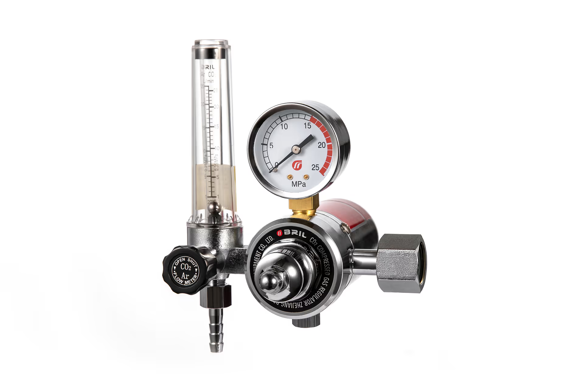
An argon flow meter vs rotameter comparison can sound like a choice between two different measuring technologies. In welding, it often is not: the clear, tapered flow tube on an argon flowmeter regulator is itself a rotameter. The useful question is whether your application needs an integrated regulator-and-flowmeter assembly or a separate variable-area meter—and whether that assembly will deliver repeatable shielding gas flow under your actual working conditions.
For a cylinder-fed TIG or MIG station, an integrated argon flowmeter regulator is usually the more practical starting point. For a plant gas line that already has appropriate pressure regulation, a separate rotameter may be the better fit. Neither choice guarantees a sound weld: gas selection, calibration conditions, hose behavior, torch setup, and drafts all affect the shielding that reaches the weld pool.
What the Two Terms Mean
What is an argon flow meter?
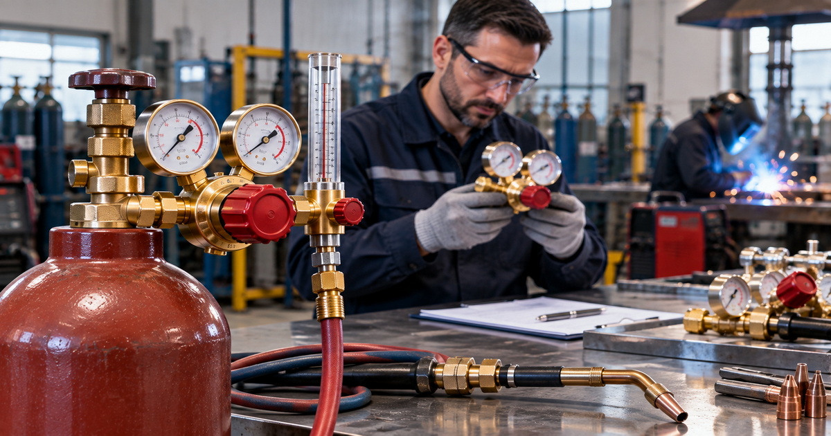
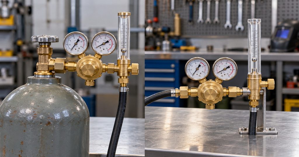
In welding catalogs, an “argon flow meter” commonly refers to a device that indicates argon flow in cubic feet per hour (CFH) or liters per minute (L/min). A cylinder-mounted flowmeter regulator combines pressure reduction with an adjustable flow indication. For example, Miller describes a single-stage MIG/TIG flowmeter regulator with an argon scale, flow-adjustment valve, and protective flow-tube features.
The name alone does not tell you how the device measures flow. A transparent tube with a moving float uses the variable-area principle; it is a rotameter. A pressure gauge marked in flow units is a different arrangement and should not be assumed to measure flow directly. When reviewing a quotation, ask for a diagram or specification that identifies the sensing method.
What is a rotameter?
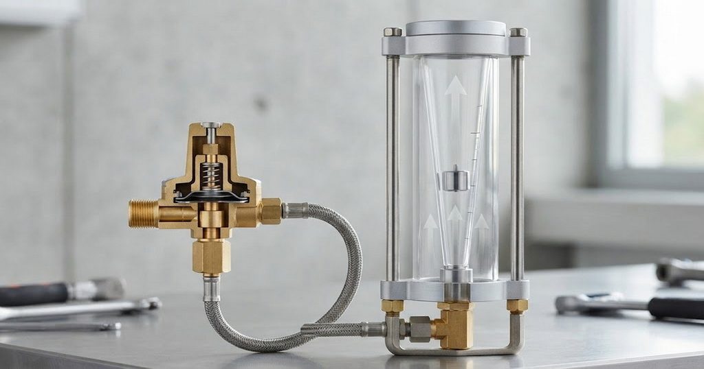
A rotameter is a variable-area flowmeter. Gas enters the narrow end of a tapered tube and lifts a float. As flow increases, the float rises until the forces acting on it reach equilibrium; its position indicates flow on a calibrated scale. Conventional float-type units normally require a vertical tube with upward flow, although some specially designed variable-area meters support other mounting positions.
A rotameter can be a standalone component in a regulated gas line or part of an integrated welding regulator. That overlap matters to buyers: comparing “argon flow meter” with “rotameter” solely by product name risks comparing a complete gas-control assembly with one of its components.
Argon Flow Meter vs Rotameter: Key Differences
The table uses “argon flowmeter regulator” to mean a cylinder-ready integrated assembly and “standalone rotameter” to mean a separate variable-area meter. Exact capabilities depend on the model and its datasheet.
| Decision point | Integrated argon flowmeter regulator | Standalone rotameter |
|---|---|---|
| Main function | Reduces supply pressure and indicates or adjusts flow in one assembly | Indicates flow; pressure control must be provided separately unless specified |
| Typical location | At a compatible cylinder outlet or regulated gas supply | In a line or panel after suitable pressure regulation |
| Measurement principle | Often a float-in-tube rotameter | Variable-area float or equivalent model-specific design |
| Installation | Check cylinder connection, inlet rating, orientation, and outlet | Check pipe connection, tube orientation, pressure, and upstream control |
| Best purchasing case | A complete, compact setup for a welding station | A configurable line or panel with existing pressure control |
| Main mistake to avoid | Assuming the flow scale remains accurate with any gas or pressure | Assuming the meter also makes high-pressure cylinder gas safe to use |
The practical distinction is system design, not an automatic accuracy advantage. Both options need a suitable flow range, a gas-appropriate scale, and operating conditions consistent with their calibration. Fluke notes that a rotameter is ideally calibrated for the same gas, pressure, and temperature at which it will be used.
Which Controls Shielding Gas More Precisely?
Pressure stability comes before fine adjustment
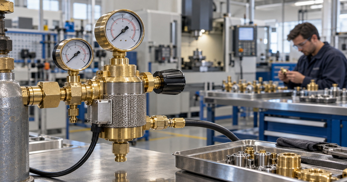
A regulator reduces and controls delivery pressure; the flowmeter shows the resulting gas flow under its operating conditions. A smooth adjustment valve is useful, but it cannot by itself correct an unsuitable upstream supply. For cylinder use, confirm the regulator’s inlet-pressure rating, cylinder connection, delivery characteristics, and intended gas before comparing the readability of two flow tubes.
Some assemblies include pressure compensation, but that phrase needs a specification, not an assumption. Harris describes one compact regulator-and-flowmeter model as pressure-compensated to a stated operating pressure; Miller identifies a back-pressure-compensated tube on an optional dual-flowmeter regulator. These are model-specific features, not proof that every welding rotameter automatically compensates for changing conditions.
Gas and scale matching affect the reading
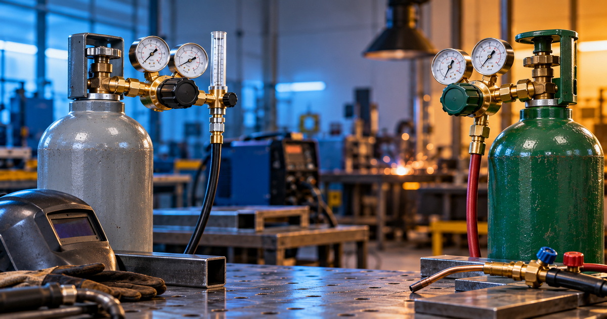
A tube marked for argon should be read on its argon scale. Do not treat an air, helium, CO₂, or argon/CO₂ scale as interchangeable merely because the units match. Fluke explains that a rotameter’s calibration depends on gas density and operating pressure and temperature; a different gas or different conditions can produce an inaccurate indication. Multi-gas tubes exist, but their distinct scales must be used as specified.
Even “standard” flow units do not make physical conditions disappear. Fluke’s calibration discussion shows why the same indicated rotameter value can require correction when actual conditions differ from scale conditions. If a welding procedure demands documented flow tolerances, request the manufacturer’s stated accuracy, reference conditions, and a relevant calibration report rather than relying on scale markings alone.
A readable number is not torch coverage
A correctly read float tells you about flow at the meter; it does not prove that the weld is shielded. Miller identifies nozzle design, gas lenses, drafts, inadequate flow, and excessive flow as factors in TIG shielding quality. It also warns that a long gas line can release a brief high-flow surge at arc start, creating turbulence even when the steady-state meter setting appears reasonable.
That is why the best precision strategy checks both the instrument and the welding result. If porosity appears, increasing the indicated CFH is not automatically the answer. Check the gas path and torch setup, then make controlled adjustments within the applicable welding procedure.
A Practical Selection Test for Buyers
First, map the complete gas path
Before requesting an OEM or ODM quotation, sketch the path from cylinder or plant outlet to torch: supply connection, regulator, flowmeter, valve, hose, welding machine, and torch. This simple step exposes missing pressure-control components and helps suppliers specify the right assembly rather than a visually similar part.
For a cylinder-fed workstation, start by evaluating a compatible regulator-and-flowmeter assembly. For an already regulated distribution line, evaluate a standalone rotameter against the line pressure, required range, fittings, and mounting space. KROHNE describes variable-area meters as useful for simple, compact gas-flow measurement, while its product range also demonstrates why ratings and installation requirements must be checked by model.
Next, define the working flow range
Choose a scale that is easy to read around your normal setpoint, not merely one with the highest maximum value. Record the process—TIG or MIG—the specified gas or blend, the required flow range, and the units your operators use. For context, Miller gives a broad typical TIG range of 10–35 CFH, while emphasizing that the correct setting depends on consumables and surrounding conditions. Treat that range as orientation, not a substitute for a welding procedure specification (WPS).
If one workstation runs pure argon and another runs a blend, specify which scale each operator will use. A clear label and legible markings can prevent an avoidable setup error. For repeat purchases, also specify whether you need identical scale artwork, float-reading instructions, and units across the product line.
Finally, compare evidence—not adjectives
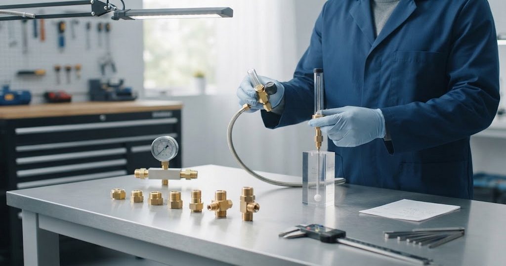
Ask each supplier to identify:
– The intended gas or gas mixture, scale units, reference conditions, and usable range.
– The regulator’s rated inlet conditions, outlet arrangement, and compatible cylinder or line connection.
– The flow tube’s material, mounting orientation, adjustment valve, and protective features.
– The stated flow accuracy, test points, inspection method, and any calibration documentation.
– The applicable product certifications or standards, with evidence for the specific model quoted.
Terms such as “precision,” “industrial grade,” and “international standard” are not test results. A useful supplier response ties each claim to a drawing, test record, datasheet, or certificate. Fluke’s guidance particularly underscores the value of recording flow alongside pressure and temperature during calibration.
Field Insight: Check the Torch, Not Just the Tube
A practical commissioning check can separate a meter-selection problem from a shielding problem. It is especially useful when a shop reports that the float looks stable but weld appearance varies.
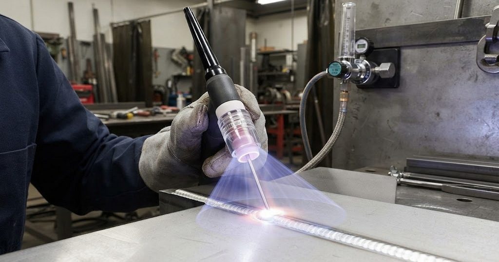
1. Confirm the approved setup. Check the WPS, gas identity, nozzle or cup, hose configuration, and the correct scale before changing the flow.
2. Inspect the gas path. Look for damaged tubing, loose connections, and torch-assembly faults using procedures approved for the equipment.
3. Observe flow during operation. Set and read the meter under flowing conditions, at eye level and in the manufacturer’s specified orientation.
4. Check the arc-start period. Compare steady flow with the first moments after gas starts; a long line may create a short surge.
5. Change one variable at a time. Test the effect of flow, draft protection, or torch consumables while following the WPS, and record the result.
This procedure is a diagnostic framework, not a universal calibration method. Fluke recommends allowing flow, pressure, and temperature to stabilize for rotameter calibration; Miller explains that both too little shielding and excessive, turbulent flow can contribute to contamination.
Three Errors That Distort Comparisons
Mistaking a flow setting for weld quality
More gas is not always safer for the weld. Miller advises using the lowest effective TIG shielding-gas flow for the application because excessive flow can increase turbulence, while insufficient flow leaves the weld pool and hot tungsten inadequately protected. A gas lens and suitable nozzle can improve coverage without simply increasing the meter setting.
Ignoring installation orientation
A conventional gravity-operated rotameter needs an upright measuring tube and upward flow. An angled installation can affect the float’s movement and reading. Do not generalize this rule to every variable-area product: KROHNE also offers specially designed models for horizontal or descending lines. Verify the quoted model’s permitted orientation.
Treating safety as a connector detail
Do not choose equipment by thread fit alone. Confirm gas service, pressure rating, and installation instructions for the complete assembly. Secure cylinders and handle regulators according to the rules that apply at the worksite; OSHA’s U.S. construction rule, for example, requires cylinders to be secured against falling while in use and specifies upright positioning with limited handling exceptions.
When Each Option Makes Sense
Choose an integrated argon flowmeter regulator when you need a compact cylinder-fed welding setup with pressure reduction and visible flow adjustment in one unit. Compare the actual argon scale, connection, adjustment behavior, and documentation—not just the product photo. Miller’s catalog illustrates that even within this category, scale options and protective features vary by model.
Choose a standalone rotameter when suitable pressure regulation already exists and the installation benefits from a separate, accessible flow indication point. Check that the selected meter matches the gas, operating conditions, flow range, and mounting position. KROHNE’s variable-area range includes both straightforward glass-tube devices and more specialized configurations, so “rotameter” alone is not a complete specification.
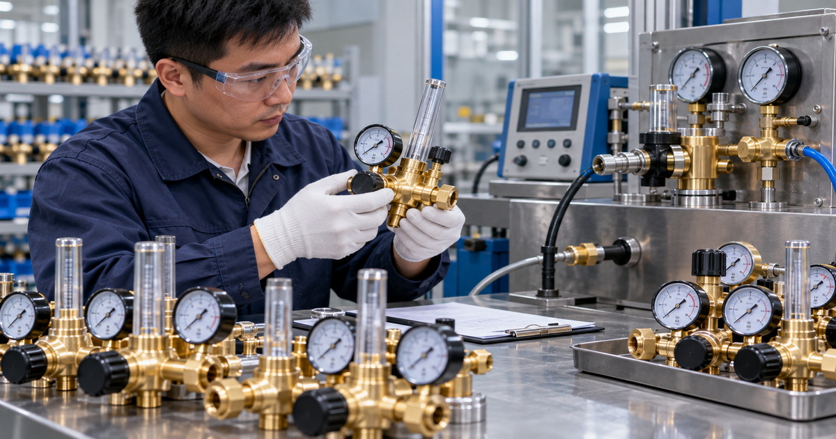
For overseas brands, wholesalers, and equipment manufacturers, the strongest OEM/ODM brief specifies the whole use case: target market, gas, supply type, connections, flow range, scale, materials, labeling, inspection requirements, and supporting documents. That gives a gas-regulator manufacturer a concrete basis for proposing a design and quoting repeatable production.
Ready to specify a shielding-gas control assembly? Send your gas type, cylinder or line connection, target flow range, operating conditions, destination market, and expected order volume to our team. Request a proposed regulator-and-flowmeter configuration, drawing, and model-specific quality documentation before approving samples.
Frequently Asked Questions
1.Is an argon flow meter the same as a rotameter?
It can be. A welding argon flowmeter with a tapered transparent tube and moving float uses the rotameter principle. “Argon flow meter” describes the gas application; “rotameter” describes the measuring technology. Check the device design before treating the names as separate categories.
2.Do I need a regulator with a standalone rotameter?
A standalone rotameter measures or indicates flow; it should not be assumed to reduce cylinder pressure. A cylinder-fed installation needs appropriately rated pressure-control equipment. Confirm the complete gas path and the manufacturer’s instructions before connecting either device.
3.Can I use an argon scale for argon/CO₂?
Not without manufacturer guidance for that exact tube and mixture. Gas properties affect a variable-area meter’s reading. Some welding flow tubes provide separate scales for argon and blends; use the specified scale rather than assuming one marked scale serves both.
4.Does a higher CFH setting always improve TIG shielding?
No. Too little flow can leave the weld unprotected, but excessive flow can create turbulence and draw surrounding air into the shielding stream. Set flow for the actual torch, consumables, conditions, and WPS; use the lowest effective rate.
5.Why does the weld show porosity when the meter looks correct?
The meter does not directly measure the shielding envelope at the weld. Drafts, torch setup, insufficient coverage, excessive flow, or an arc-start surge can affect the gas that reaches the pool. Inspect the system and change one factor at a time rather than assuming the indicated setting proves adequate shielding.
6.Can a rotameter be installed horizontally?
A conventional gravity-operated float-in-tube rotameter normally requires vertical installation with upward flow. Some specially engineered variable-area meters permit horizontal or downward installation. Follow the specification for the exact model supplied.
References
1. Fluke Calibration, “[Rotameter Calibration].” Explains variable-area measurement, gas and operating-condition effects, orientation, and calibration practice. [fluke]
2. KROHNE, “[Variable Area Flowmeters].” Describes the rotameter principle, applications, installation, limitations, and model-specific configurations. [krohne]
3. Miller Electric, “[Medium-Duty Single-Stage Flowmeter Regulators].” Product example covering welding-gas scales, flow adjustment, and assembly features. [millerwelds]
4. Miller Electric, “[Best Practices for Proper Shielding Gas in TIG Welding].” Guidance on typical TIG flow, turbulence, consumables, and gas-line behavior. [millerwelds]
5. Harris Products Group, “[Model 355-2 Flowmeter].” Manufacturer description of an integrated, pressure-compensated flowmeter regulator; model details should be reconfirmed against a current datasheet before purchase. [harrisproductsgroup]
6. U.S. Occupational Safety and Health Administration, “[29 CFR 1926.350—Gas Welding and Cutting].” U.S. construction-sector cylinder-handling and welding/cutting safety requirements. [osha]
Hot Tags: Argon Flow Meter, Argon Rotameter, Argon Flowmeter Regulator, Welding Gas Flowmeter, TIG Welding Flowmeter, MIG Welding Flowmeter, Shielding Gas Flow Meter, Argon Flow Meter Manufacturer, Welding Gas Regulator Supplier, OEM Argon Flowmeter Regulator