Content Menu
● Why an Argon Regulator Matters in TIG Welding
● What Is an Argon Regulator for TIG Welding?
>> Regulator vs. Flowmeter: What Is the Difference?
● Key Specifications When Choosing a TIG Argon Regulator
>> 1. Correct Gas Compatibility
>> 2. Inlet Connection Standard
>> 3. Flow Range and Readability
>> 4. Single-Stage or Dual-Stage Design
>> 5. Pressure Gauges and Flowmeter Accuracy
● Recommended TIG Argon Flow Rates
>> Practical Example: Diagnosing Weld Discoloration
● How to Set Up an Argon Regulator Safely
>> 2. Back Out the Adjustment Knob
>> 5. Open the Cylinder Valve Carefully
>> 7. Set Gas Flow While Gas Is Flowing
● Common Argon Regulator Problems and Solutions
● How OEM Buyers Should Evaluate an Argon Regulator Manufacturer
>> Material and Construction Quality
>> Inspection and Testing Requirements
>> OEM and ODM Customization Opportunities
● Why Stable Pressure Control Improves Welding Results
● Choose a Reliable Argon Regulator Supplier
>> 1. What is the best argon regulator for TIG welding?
>> 2. What flow rate should I use for TIG welding with argon?
>> 3. Can I use a CO₂ regulator for argon?
>> 4. Is a dual-stage argon regulator worth it?
>> 5. Why does my TIG weld have porosity even when argon is flowing?
>> 6. How do I know whether my argon regulator is leaking?
>> 7. Can an argon regulator be customized for my brand?
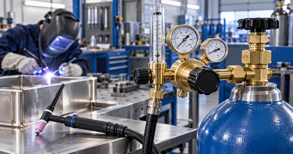
Choosing the right argon regulator for TIG welding is not simply a matter of connecting a cylinder and turning a knob. The regulator directly affects shielding-gas consistency, arc stability, weld appearance, argon consumption, and the repeatability of production results.
For TIG welding operations, a high-quality argon gas regulator should provide stable outlet pressure, accurate flow adjustment, a correct cylinder connection, durable materials, and dependable performance as cylinder pressure decreases. For welding-equipment brands, distributors, and industrial gas-control buyers, those requirements also need to be supported by consistent manufacturing, inspection, and OEM/ODM customization capability.
Why an Argon Regulator Matters in TIG Welding
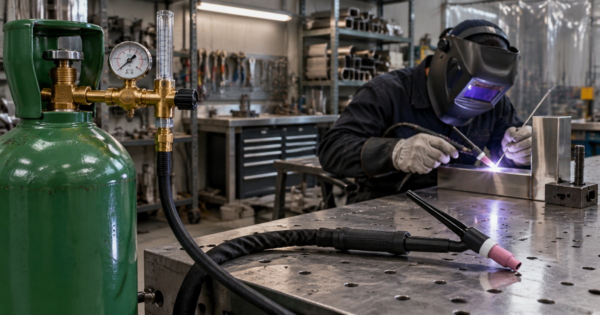
TIG welding commonly uses 100% argon as the shielding gas because it helps protect the molten weld pool and tungsten electrode from atmospheric contamination. Miller notes that 100% argon is the most widely applicable shielding gas for TIG welding, while the required flow rate varies by consumables, torch setup, and environmental conditions.
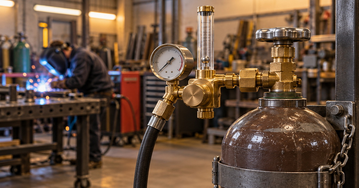
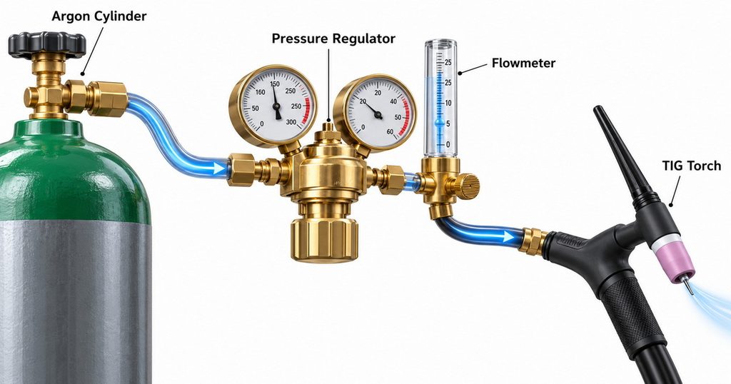
The regulator is the device that reduces high cylinder pressure to a usable, controlled output. In practical TIG welding, it often works together with a flowmeter or flow gauge so the operator can set shielding-gas flow in cubic feet per hour (CFH) or liters per minute (L/min).
A weak, inaccurate, or poorly matched regulator can cause several costly problems:
– Inconsistent gas flow, especially as cylinder pressure declines
– Porosity or oxidation in the weld bead
– Unnecessary argon waste
– Unstable arc starts or contamination of the tungsten
– Unreliable welding parameters between operators or shifts
– Safety risks caused by incompatible connections or damaged fittings
For a fabrication shop, these issues can reduce productivity. For an OEM welding-equipment brand, they can become warranty claims, negative distributor feedback, and damage to product reputation.
What Is an Argon Regulator for TIG Welding?
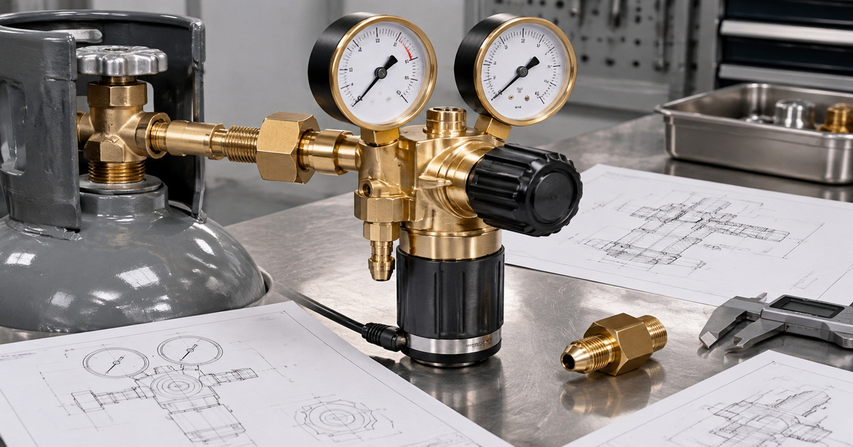
An argon regulator is a pressure-control device fitted between an argon cylinder and the TIG welding system. Its primary role is to reduce the cylinder’s high inlet pressure to a lower, stable working pressure.
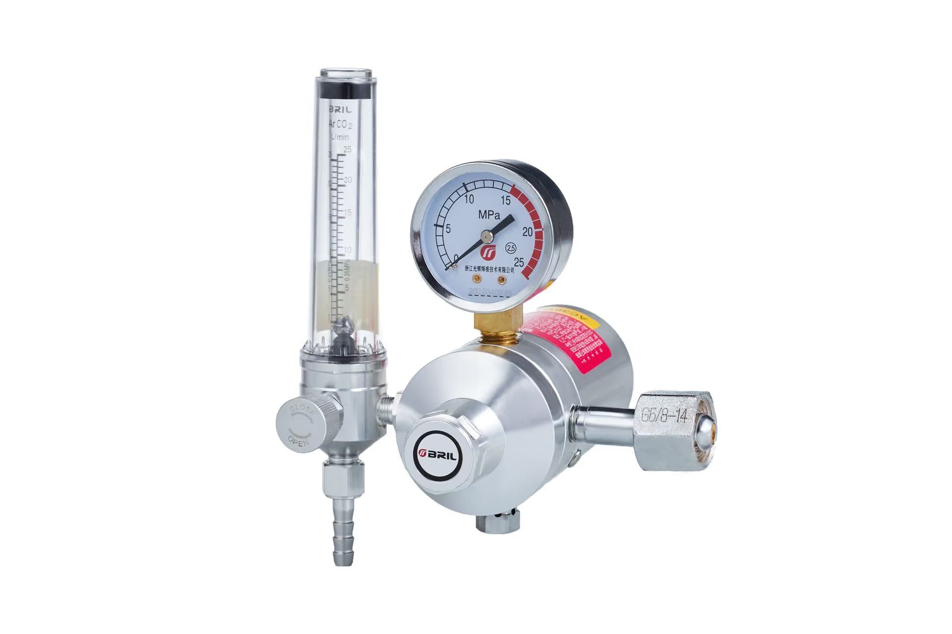
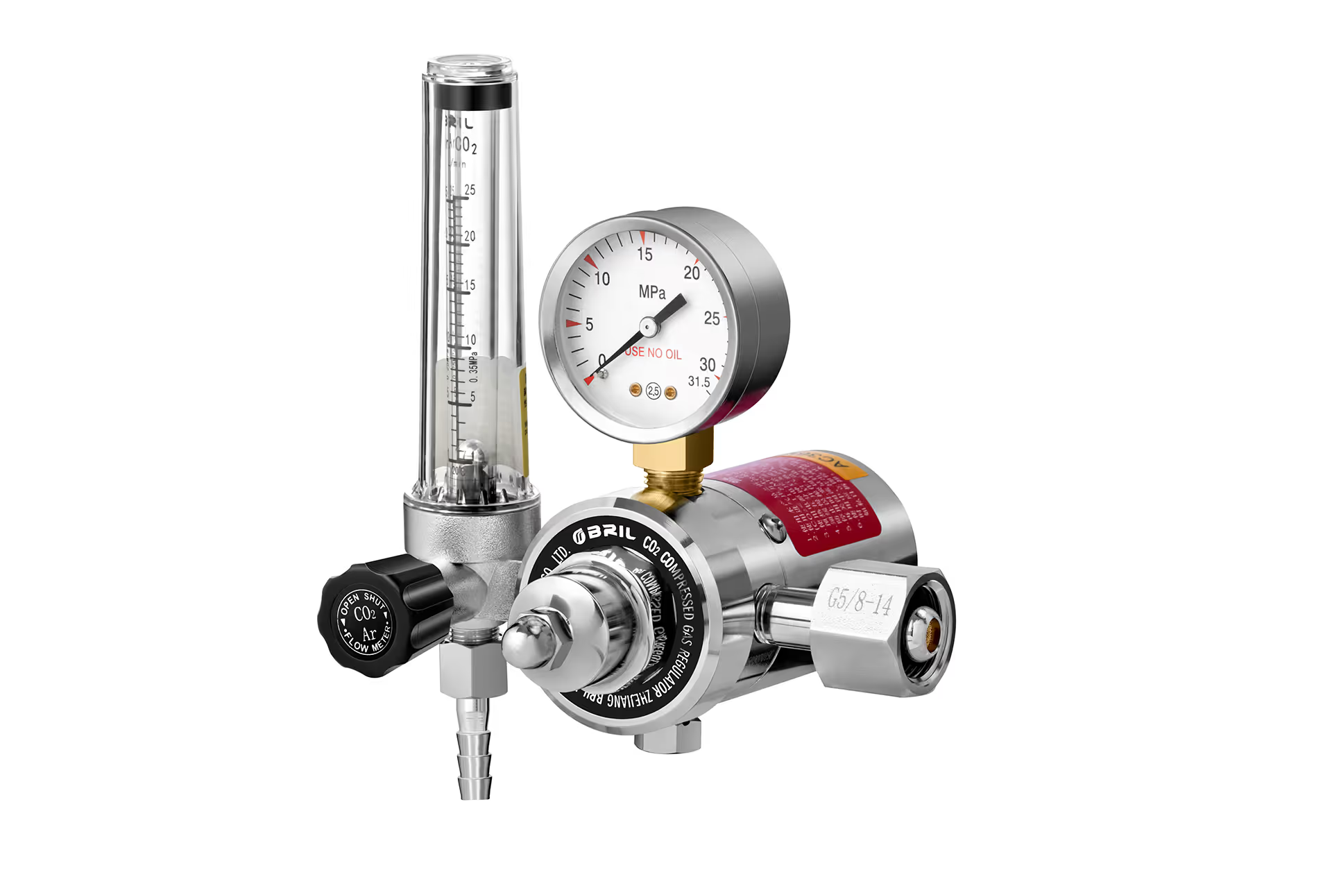
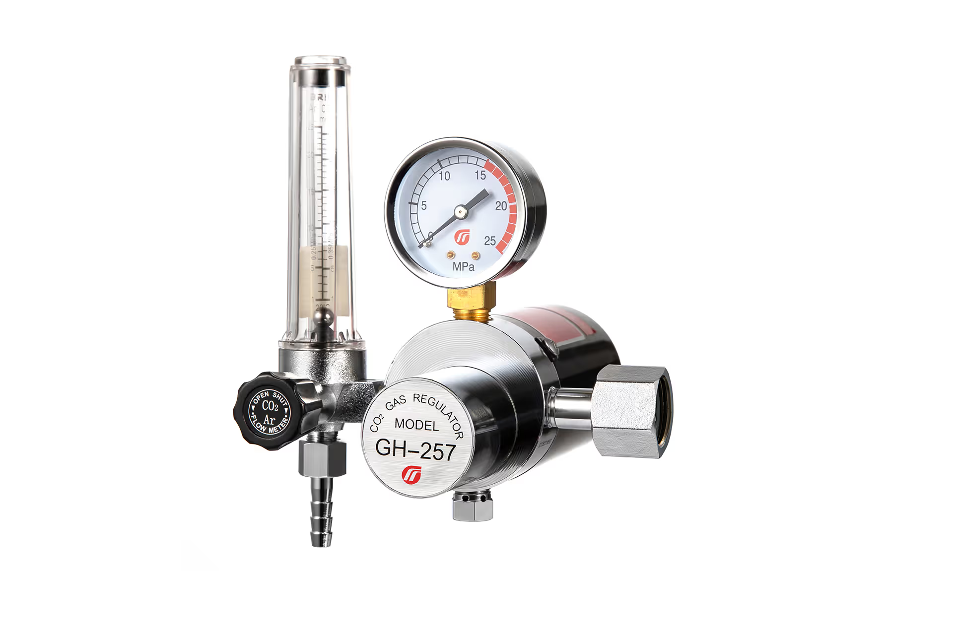
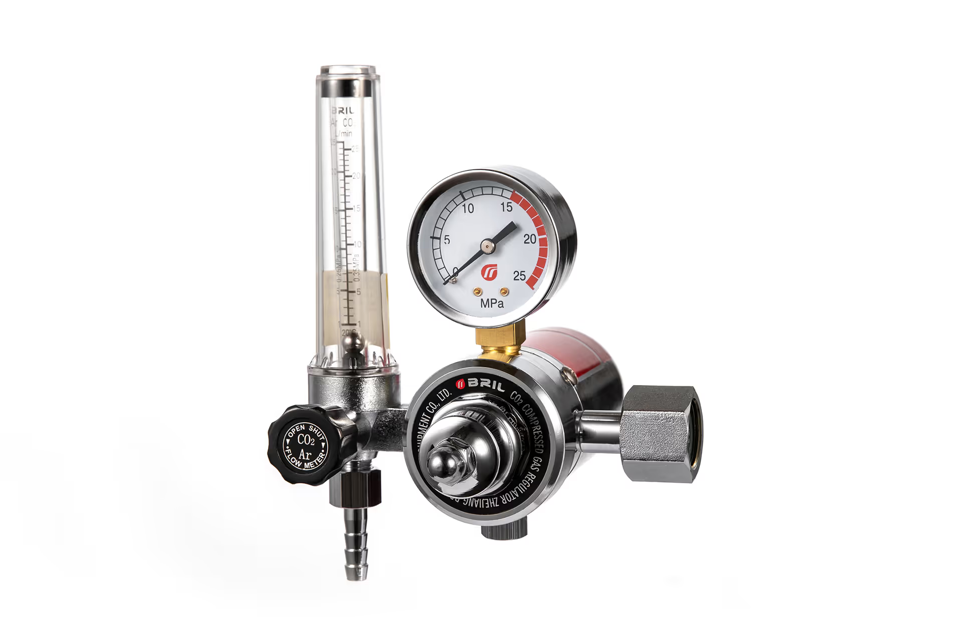
A TIG argon regulator may include:
– A cylinder inlet connection
– A high-pressure inlet gauge showing cylinder contents or cylinder pressure
– A low-pressure outlet gauge or a flowmeter
– A pressure-adjustment knob
– A hose barb or outlet fitting
– Safety relief components
– A brass regulator body, bonnet, valve seat, and internal pressure-control assembly
In many TIG applications, buyers prefer a flowmeter regulator rather than a conventional pressure-gauge regulator. This is because TIG shielding gas is usually selected by flow rate, such as 15 CFH or 20 CFH, rather than by outlet pressure alone.
Regulator vs. Flowmeter: What Is the Difference?
| Component | Primary Function | Why It Matters for TIG Welding |
|---|---|---|
| Pressure regulator | Reduces cylinder pressure to a controlled outlet pressure | Protects the system from uncontrolled high-pressure gas |
| Flow gauge regulator | Displays gas flow through a gauge | Useful for basic TIG gas-flow adjustment |
| Flowmeter regulator | Uses a transparent tube and floating ball to show gas flow | Often provides clearer, more direct CFH or L/min adjustment |
| Two-stage regulator | Uses two pressure-reduction stages | Helps maintain more consistent outlet pressure as cylinder pressure falls |
For general TIG work, a good flowmeter regulator provides practical control and easy setup. For continuous production, automated cells, laboratory environments, critical stainless-steel or aluminum work, and other demanding applications, a dual-stage argon regulator can offer stronger pressure stability throughout the life of the cylinder.
Key Specifications When Choosing a TIG Argon Regulator
The best regulator is not always the model with the highest gauge range or the lowest unit cost. It is the model that matches the gas type, cylinder connection, required flow range, duty cycle, and local market standards.
1. Correct Gas Compatibility
The regulator must be specifically designed for argon or for compatible inert gases, depending on its labeling, connection standard, seals, and intended service.
Argon regulators are often also suitable for helium or certain argon-based shielding-gas mixtures when the connection and manufacturer’s specification permit it. However, users should never assume that every regulator is interchangeable across gases.
Different gases can use different valve outlets, thread forms, inlet fittings, sealing requirements, flow characteristics, and safety expectations. For example, oxygen regulators must be kept free from oil, grease, and combustible contamination. Safety guidance also warns users never to force fittings or use connections that do not match the cylinder valve outlet.
Buyer checklist:
– Confirm the gas type: argon, argon/CO₂ mix, helium, nitrogen, oxygen, acetylene, propane, or CO₂
– Verify the required cylinder inlet standard for the destination market
– Match outlet fittings to the hose and welding machine configuration
– Confirm seal materials and internal components are suitable for the intended gas
– Do not use adapters as a substitute for correct gas-specific regulator design unless they are approved for the application
2. Inlet Connection Standard
The cylinder connection is one of the most important purchasing details. A regulator may be technically excellent but unusable if its inlet fitting does not match the customer’s local cylinders.
Common connection systems may include:
– CGA connections in the United States and Canada
– DIN-based or national standards in parts of Europe
– BS, EN, JIS, Australian, South African, or other regional fittings
– Custom cylinder-valve interfaces in specific industrial-gas markets
For welding and cutting equipment, industry guidance requires regulators to be used only for the gases and pressures for which they are intended, and it requires regulator inlet connections to be marked with an identifying CGA number in applicable U.S. contexts.
For overseas brands and distributors, this makes OEM configuration especially important. A professional manufacturer should be able to provide the correct inlet nut, stem, washer, nipple, outlet fitting, label, packaging, and instruction manual for the intended market.
3. Flow Range and Readability
For TIG welding, the flowmeter range should match real operating needs. A flowmeter with too broad a range can make fine adjustment more difficult, while one with too narrow a range may not support larger cups, gas lenses, back-purging, or draft-prone environments.
Miller states that TIG gas flow commonly falls between 10 and 35 CFH, depending on consumables and environmental conditions. It also recommends using the lowest effective flow rate to preserve laminar flow and reduce contamination risk.
A typical TIG argon flowmeter may offer a range such as:
– 0–25 CFH
– 0–30 CFH
– 0–40 CFH
– 0–50 CFH
– 0–15 L/min
– 0–25 L/min
A clear acrylic flow tube, easy-to-read scale, stable float ball, and durable protective guard can improve daily usability in workshop conditions.
4. Single-Stage or Dual-Stage Design
A single-stage regulator reduces pressure in one step. It is widely used in standard welding operations because it is compact, economical, and suitable for many routine applications.
A dual-stage regulator reduces cylinder pressure in two steps. This design can help limit output-pressure changes as the cylinder empties. It is especially relevant when stable delivery pressure matters over long operating periods.
| Factor | Single-Stage Argon Regulator | Dual-Stage Argon Regulator |
|---|---|---|
| Construction | One pressure-reduction stage | Two pressure-reduction stages |
| Cost | Typically lower | Typically higher |
| Size and weight | Usually more compact | Often larger and heavier |
| Outlet stability as cylinder pressure drops | May require more adjustment | Generally more stable |
| Typical use | General TIG welding and workshop use | Precision welding, industrial production, lab work, critical processes |
| OEM positioning | Entry-level to mid-range product lines | Premium or professional product lines |
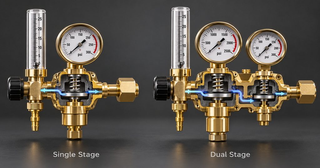
For a welding distributor, offering both options can create a clear product ladder: a reliable single-stage regulator for everyday welders and a dual-stage argon regulator for industrial customers who prioritize stable gas control.
5. Pressure Gauges and Flowmeter Accuracy
A professional TIG regulator should provide measurements that are clear, repeatable, and practical in real workshop conditions.
Look for:
– Large, readable dial faces
– Protective gauge boots or durable gauge housing
– Appropriate pressure range for the cylinder service
– Stable pointer movement
– Accurate flowmeter scale
– Secure gauge threads and leak-resistant assembly
– Clearly marked units, such as PSI, bar, MPa, CFH, or L/min
It is also important to distinguish cylinder pressure from gas flow rate. The high-pressure gauge generally indicates remaining cylinder pressure, while the flowmeter shows the amount of argon delivered to the torch during operation.
Recommended TIG Argon Flow Rates
Gas flow should be selected according to cup size, torch setup, material, weld position, joint design, airflow, tungsten extension, and use of a gas lens. There is no single “perfect” setting for every TIG weld.
As a practical starting point, many TIG welding operations use approximately 15–25 CFH. Meritus Gas notes that typical TIG setups often run in this range, while higher flow may be required where shielding conditions are more demanding.
| TIG Welding Condition | Typical Starting Flow | Notes |
|---|---|---|
| Thin steel or stainless steel indoors | 10–15 CFH | Start low and increase only if shielding is insufficient |
| General steel or stainless TIG welding | 15–20 CFH | Common range for many workshop applications |
| Aluminum TIG welding | 15–25 CFH | Flow may increase with larger cups or higher heat input |
| Large cup or extended tungsten | 20–30 CFH | Verify coverage without creating turbulence |
| Gas lens setup | Often lower than a standard cup | Gas lenses can improve flow distribution |
| Light drafts or open work areas | Increase carefully | Use screens when possible rather than excessive flow |
| Pipe work or stainless back-purging | Application-specific | Requires separate purge planning and monitoring |
The key principle is simple: more gas is not always better. Excessive flow can create turbulence that pulls surrounding air into the shielding zone. The result may be discoloration, oxidation, porosity, or unstable arc behavior even though the operator believes they are “adding protection.”
Practical Example: Diagnosing Weld Discoloration
A TIG operator sees blue-gray heat tint and occasional porosity on stainless-steel joints. Their first reaction is to turn the flowmeter from 18 CFH to 35 CFH.
That may not solve the real problem.
A better diagnostic sequence is:
1. Check whether the cylinder contains the correct argon grade.
2. Inspect the regulator, hose, torch body, and fittings for leaks.
3. Confirm that the flow is measured while gas is actually flowing.
4. Inspect the cup, collet body, gas lens, and O-rings.
5. Reduce drafts using welding screens or a protected work area.
6. Verify post-flow time and torch angle.
7. Adjust flow gradually rather than making a large increase.
This approach reduces wasted argon and addresses root causes instead of treating every shielding issue as a flow-rate problem.
How to Set Up an Argon Regulator Safely
Compressed gas systems contain high pressure and must be handled carefully. OSHA identifies hazards associated with compressed gases, including oxygen displacement, fire, explosion, toxic exposure, and the physical hazards of high-pressure systems.
Use the following general procedure alongside your equipment manual, local regulations, and site safety procedures.
1. Secure the Cylinder
Keep the argon cylinder upright and secured with a chain, strap, or approved cylinder stand. Never allow a cylinder to stand unsecured.
Before installation, visually inspect the cylinder valve, regulator threads, gauge faces, flowmeter, hose, and fittings for visible damage.
2. Back Out the Adjustment Knob
Before attaching the regulator, turn the pressure-adjustment knob counterclockwise until it is fully released. This helps ensure that gas does not immediately flow through the regulator when the cylinder valve is opened.
3. Check the Connection
Confirm that the regulator inlet connection matches the cylinder outlet. Never force threads that do not fit. Do not use an oxygen regulator, fuel-gas regulator, or incompatible inert-gas regulator in place of the correct argon regulator.
4. Attach the Regulator
Attach the inlet nut to the cylinder valve by hand, then tighten it using the correct tool. Avoid overtightening, which can damage threads, seals, or fittings.
5. Open the Cylinder Valve Carefully
Stand to the side of the regulator outlet—not directly in front of it—when opening the valve. OSHA construction rules state that, before a regulator is connected, the valve may be opened slightly and closed immediately to clear dust or dirt, and the person performing this action should stand to the side of the outlet.
Open the cylinder valve gradually according to the cylinder supplier’s guidance.
6. Test for Leaks
Use an approved leak-detection solution on relevant joints and fittings. Never use an open flame to check for leaks.
7. Set Gas Flow While Gas Is Flowing
Activate the TIG torch gas flow or use the welding machine’s gas-test function. Then adjust the flowmeter to the required CFH or L/min setting while gas is actually flowing through the system.
8. Shut Down Correctly
When work is complete:
1. Close the cylinder valve.
2. Allow gas trapped in the line and regulator to bleed off.
3. Back out the regulator adjustment knob.
4. Store the equipment according to site safety requirements.
OSHA notes that before removing a regulator from a cylinder valve, the cylinder valve should be closed and gas released from the regulator.
Common Argon Regulator Problems and Solutions
| Problem | Likely Cause | Recommended Action |
|---|---|---|
| Flowmeter ball does not rise | Cylinder valve is closed, empty cylinder, blocked line, faulty flowmeter | Check cylinder contents, valve position, hose condition, and gas-test function |
| Gas flow fluctuates | Damaged regulator, loose fitting, unstable cylinder pressure, contamination | Perform leak check, inspect gauges and fittings, service or replace regulator if needed |
| Excessive argon consumption | Flow set too high, leaks, long post-flow, poor torch setup | Inspect leaks, optimize flow, confirm post-flow settings |
| Porosity in weld | Drafts, inadequate shielding, contamination, leak, incorrect gas | Check gas quality, cup, O-rings, torch angle, hose, and local airflow |
| Regulator will not connect | Incorrect inlet fitting or damaged thread | Verify cylinder outlet standard; never force the connection |
| Gauge reading is abnormal | Damaged gauge, mechanical shock, internal fault | Remove from service and inspect or replace through a qualified supplier |
| Frosting or freezing | Often associated with high gas demand or CO₂ service rather than normal argon flow | Use a regulator designed for the gas and duty cycle; consider heated CO₂ regulators where appropriate |
How OEM Buyers Should Evaluate an Argon Regulator Manufacturer
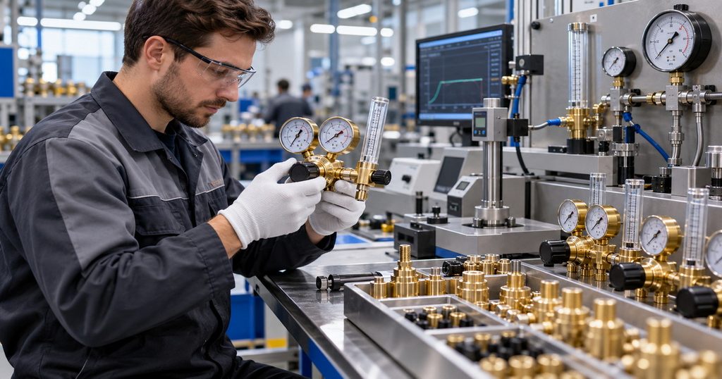
For overseas brands, wholesalers, importers, and welding-equipment distributors, regulator selection should go beyond product appearance. A regulator body may look similar across suppliers while internal materials, assembly control, leak testing, calibration, thread accuracy, and final inspection differ significantly.
A capable gas regulator manufacturer should support both product performance and commercial scalability.
Material and Construction Quality
Brass remains a common material for industrial gas regulator bodies because it offers good machinability, corrosion resistance, and durability in appropriate gas-control applications. Buyers should ask about:
– Brass grade and material traceability
– Forged versus cast body construction
– Valve-seat material
– Diaphragm material and thickness
– Spring quality and corrosion resistance
– Gauge quality and calibration process
– Thread machining accuracy
– Hose-barb material and connection strength
A robust external finish is helpful, but internal control components are equally important. The valve seat, diaphragm, spring, and pressure-control geometry determine whether the regulator delivers stable performance over repeated cycles.
Inspection and Testing Requirements
A professional supplier should have documented inspection processes, not only final visual checks. Consider asking for evidence of:
– Incoming-material inspection
– Thread and fitting verification
– Leakage testing
– Pressure-performance testing
– Flow-performance testing
– Gauge inspection or calibration verification
– Assembly torque control
– Random batch sampling
– Final appearance inspection
– Packaging inspection before shipment
ISO 2503 addresses pressure regulators and pressure regulators with flow-metering devices for gas cylinders used in welding, cutting, and allied processes. Buyers should confirm which certifications, test reports, and standards are applicable to their target market rather than relying on general claims alone.
OEM and ODM Customization Opportunities
A strong OEM/ODM manufacturer can help a distributor build a coherent, market-specific product range. Possible customization options include:
– Customized inlet fittings for local cylinder standards
– CFH or L/min flowmeter scales
– PSI, bar, or MPa pressure gauge units
– Branded gauge faces
– Laser-marked logos
– Custom regulator colors or protective gauge covers
– Private-label packaging
– Multilingual user manuals
– Retail display packaging
– Different flow ranges
– Single-stage and dual-stage product variants
– Product bundles with hoses, adapters, flashback arrestors, or TIG accessories
For example, a North American private-label welding brand may need a CGA-compatible argon flowmeter regulator with CFH scale, PSI gauges, English/French packaging, and retail-ready barcode labeling. A European distributor may require a different inlet standard, bar-based gauges, L/min flowmeter scale, localized warning labels, and CE-related documentation where applicable.
Why Stable Pressure Control Improves Welding Results
In TIG welding, shielding gas is not only a consumable. It is part of the welding process.
Stable gas control supports:
– Cleaner weld appearance
– Better protection of the molten weld pool
– More consistent tungsten condition
– Reduced risk of atmospheric contamination
– Improved repeatability between operators
– Lower argon waste
– Better process documentation for production welding
A regulator cannot compensate for every welding problem. It cannot correct contaminated base metal, improper tungsten preparation, poor joint fit-up, an unsuitable torch angle, or severe wind exposure. However, it is a foundational part of a stable shielding-gas system.
For industrial users, the goal should be repeatable gas delivery—not merely visible gas flow.
Choose a Reliable Argon Regulator Supplier
The right argon regulator for TIG welding should match your cylinder standard, gas type, desired flow range, welding environment, and quality expectations. For occasional workshop use, a dependable single-stage flowmeter regulator may be sufficient. For industrial fabrication, production welding, or branded equipment programs, stable pressure control, consistent materials, verified testing, and OEM customization become much more important.
As a professional gas regulator manufacturer and supplier, we provide industrial gas-control solutions for welding, cutting, fabrication, and distribution markets. Our product range includes:
– Argon regulators for TIG and MIG welding
– CO₂ regulators and heated CO₂ regulators
– Oxygen regulators
– Acetylene regulators
– Propane regulators
– Nitrogen regulators
– Dual-stage gas regulators
– Customized welding gas regulators for OEM and ODM programs
We focus on precision manufacturing, durable brass components, stable pressure control, strict quality inspection, and customized solutions for overseas brands, wholesalers, distributors, and industrial equipment manufacturers.
Frequently Asked Questions
1. What is the best argon regulator for TIG welding?
For most TIG welding applications, a flowmeter-style argon regulator is the most practical choice because it lets the user adjust shielding gas directly in CFH or L/min. The best option depends on cylinder connection, expected flow range, usage frequency, and whether the application needs a single-stage or dual-stage design.
2. What flow rate should I use for TIG welding with argon?
Many TIG welding jobs begin in the range of 15–25 CFH, but the correct setting depends on cup size, material, torch setup, welding position, airflow, and gas lens use. Start with the lowest effective flow rate and adjust based on shielding performance.
3. Can I use a CO₂ regulator for argon?
You should use a regulator specifically designed and configured for the gas and cylinder connection in your application. Even if two regulators look similar, their inlet fittings, operating ranges, flow characteristics, labels, and internal components may differ. Always verify compatibility with the gas supplier and regulator manufacturer.
4. Is a dual-stage argon regulator worth it?
A dual-stage argon regulator is often worthwhile when stable output pressure is important over long production runs or as cylinder pressure falls. It is commonly selected for precision welding, industrial production, laboratory processes, and premium welding-equipment product lines.
5. Why does my TIG weld have porosity even when argon is flowing?
Porosity may be caused by insufficient shielding, excessive flow turbulence, gas leaks, drafts, contaminated base metal, incorrect torch angle, damaged torch consumables, poor gas purity, or moisture in the system. Check the full shielding-gas path instead of only increasing CFH.
6. How do I know whether my argon regulator is leaking?
Apply an approved leak-detection solution to the regulator connection, hose fitting, and other joints while the system is pressurized. Bubbling can indicate a leak. Do not use an open flame. If the regulator body, gauge, or threaded fittings are damaged, remove the unit from service.
7. Can an argon regulator be customized for my brand?
Yes. A qualified OEM/ODM regulator manufacturer can customize inlet connections, flowmeter scales, pressure units, gauge faces, logos, labels, packaging, manuals, hose fittings, and product configurations to meet the requirements of different export markets.
References
1. MillerWelds. “[Best Practices for Proper Shielding Gas in TIG Welding].” Guidance on TIG shielding-gas selection, typical flow ranges, flowmeter use, and minimizing turbulent gas flow.
2. Occupational Safety and Health Administration (OSHA). “[Compressed Gas and Equipment—Overview].” Overview of hazards associated with compressed gases and applicable occupational safety requirements.
3. Occupational Safety and Health Administration (OSHA). “[29 CFR 1926.350—Gas Welding and Cutting].” Requirements and safety guidance covering regulator connection, cylinder-valve handling, and regulator removal.
4. Washington State University. “[Compressed Gases and Gas Cylinders].” Safety instructions covering regulator adjustment, compatible cylinder connections, oxygen cleanliness, and connection handling.
5. Oregon OSHA. “[Welding and Cutting Code Revision].” Guidance on regulator suitability, CGA identification, inspection of fittings, and gas-specific regulator use.
6. International Organization for Standardization (ISO). “[ISO 2503:2009—Gas Welding Equipment: Pressure Regulators and Pressure Regulators with Flow-Metering Devices for Gas Cylinders].” International standard covering pressure regulators and flow-metering regulator devices for welding gas cylinders.
7. Meritus Gas Partners. “[Determine the Gas Flow Rate Needed for Your Weld].” Practical information on TIG shielding-gas flow ranges, the relationship between flow settings and welding conditions, and gas-quality considerations.
Hot Tags: Argon Regulator, TIG Welding Regulator, Argon Flowmeter Regulator, Dual Stage Gas Regulator, Welding Gas Regulator, Industrial Gas Regulator, TIG Welding Gas Flow, Argon Gas Control, OEM Gas Regulator, Gas Regulator Manufacturer