Content Menu
● CO₂ Flowmeter vs. Argon Flowmeter at a Glance
● Why Gas-Specific Calibration Matters
>> CO₂ and argon do not flow identically
>> Regulator compatibility is as important as flow accuracy
● CO₂ Flowmeter for MIG Welding
>> Where pure CO₂ performs well
>> Typical CO₂ MIG flow settings
● Argon Flowmeter for MIG and TIG Welding
>> Argon flowmeter for MIG welding
>> Argon flowmeter for TIG welding
● MIG vs. TIG: Which Flowmeter Should You Specify?
● Practical Setup Checklist for Welders
● How OEM Buyers Can Evaluate a Welding Gas Regulator Supplier
● FAQ
>> 1. Can I use an argon flowmeter for pure CO₂?
>> 2. Is pure CO₂ suitable for TIG welding?
>> 3. What is the best gas flow rate for MIG welding?
>> 4. What is the normal argon flow rate for TIG welding?
>> 5. Why does my weld have porosity even when the flowmeter is set high?
>> 6. What is the difference between a gas regulator and a flowmeter?
>> 7. Do I need a dual-flowmeter regulator for TIG welding?
Choosing the right gas flowmeter regulator is not simply a matter of connecting a cylinder and setting a number. A CO₂ flowmeter and an argon flowmeter are calibrated for different gas properties, cylinder connections, welding processes, and shielding-gas requirements. For reliable MIG and TIG weld quality, the flowmeter must match the gas, the regulator must fit the cylinder valve, and the flow setting must suit the torch, nozzle, material, and working environment.
For manufacturers, distributors, and welding-equipment brands, specifying the correct CO₂ regulator flowmeter or argon flowmeter regulator can reduce gas waste, prevent connection errors, and support more consistent welding results across customer applications.
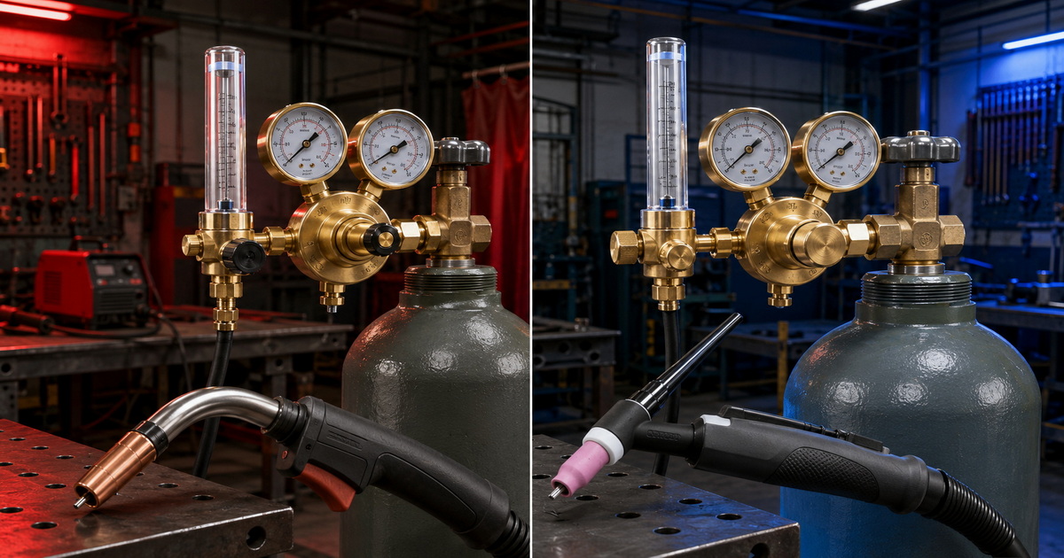
CO₂ Flowmeter vs. Argon Flowmeter at a Glance
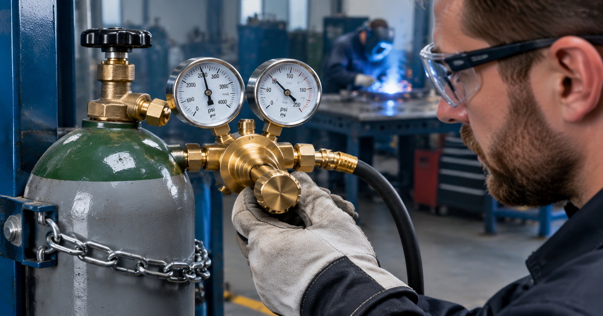
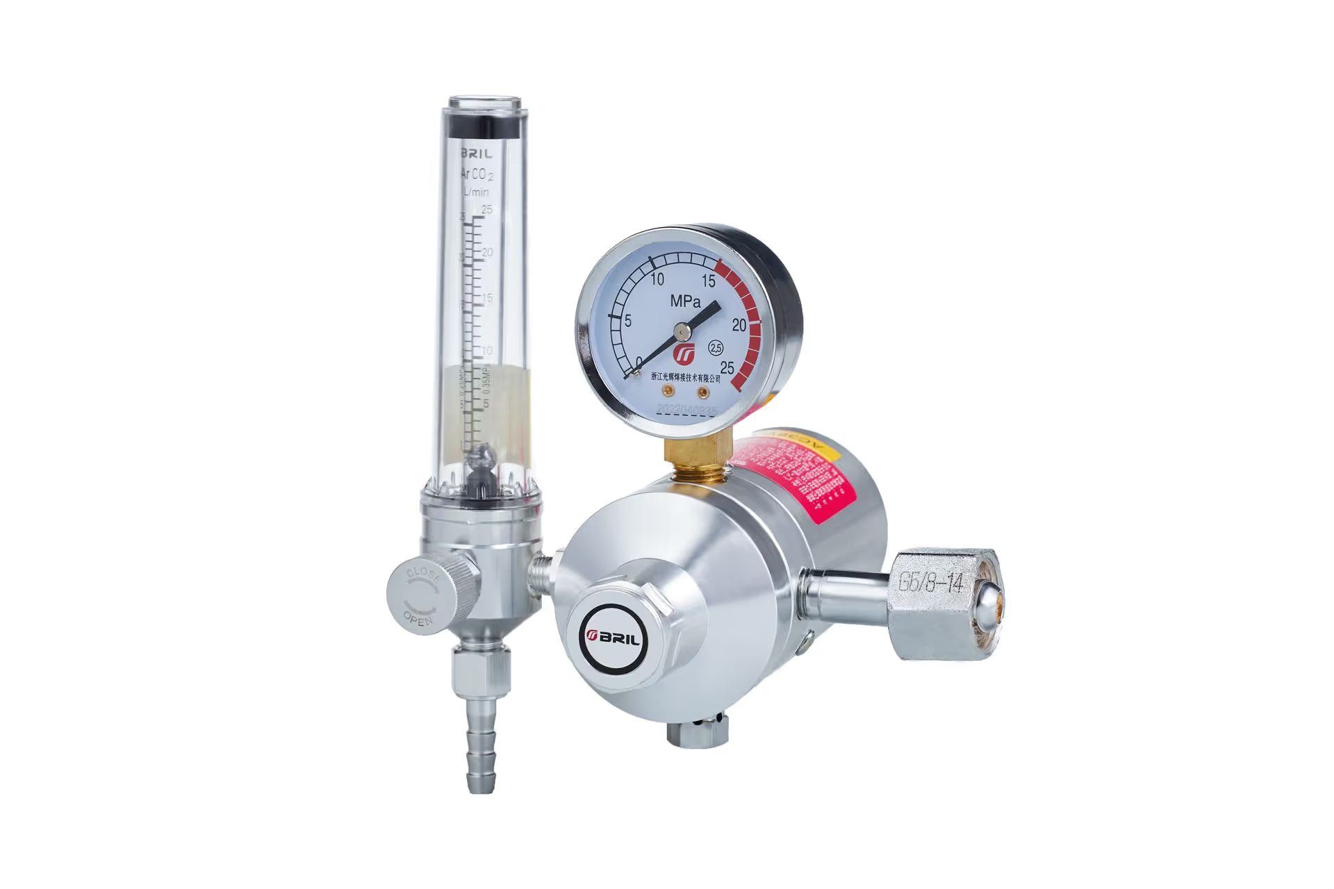
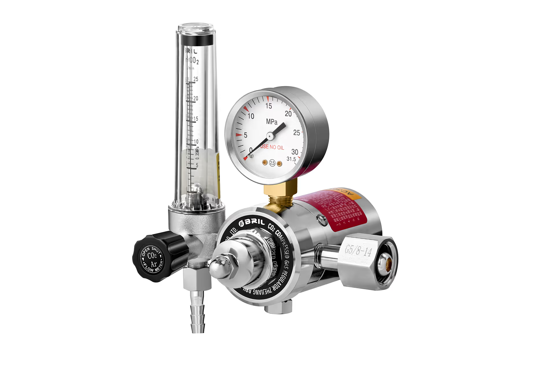
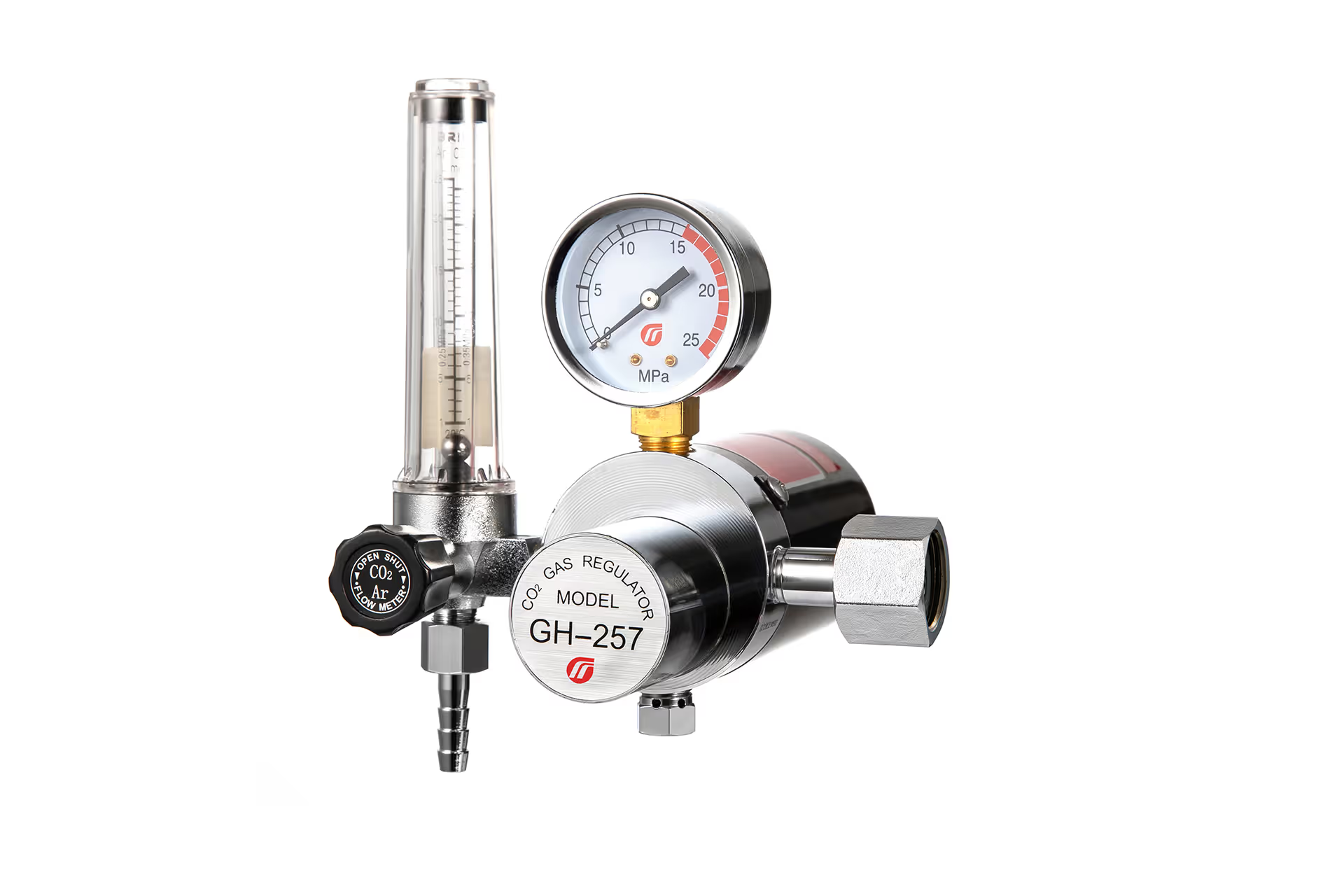
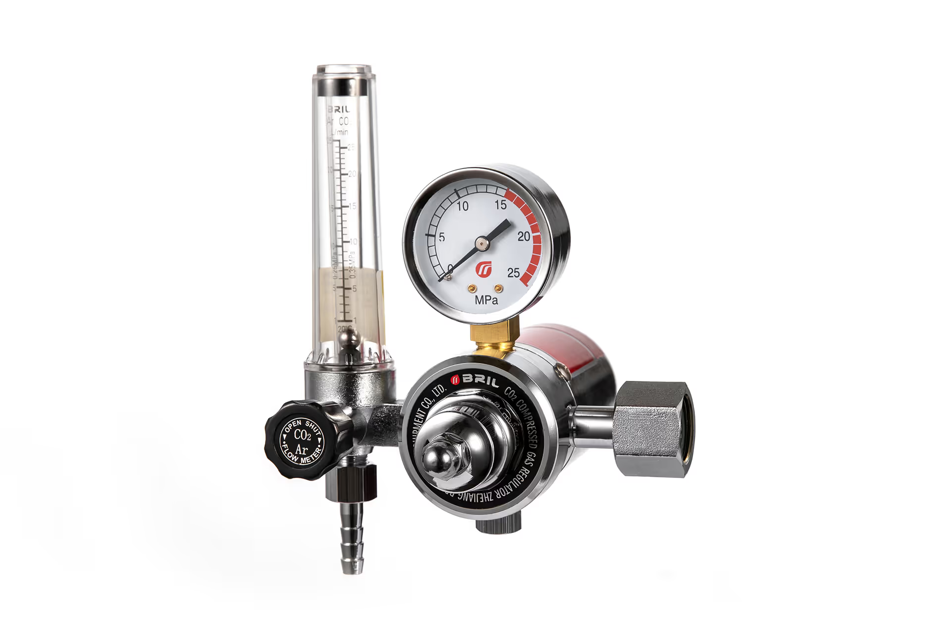
A flowmeter regulator performs two jobs:
1. It reduces the high pressure inside a gas cylinder to a controlled working pressure.
2. It measures and adjusts the shielding-gas flow supplied to the welding torch.
The important point is that a flow tube and scale are not automatically interchangeable between gases. The float position is influenced by gas density and flow characteristics. Therefore, a flowmeter calibrated for argon or argon/CO₂ mixtures should not be treated as a precision measurement device for pure CO₂ unless the manufacturer specifically rates and calibrates it for CO₂.
| Feature | CO₂ Flowmeter Regulator | Argon Flowmeter Regulator |
|---|---|---|
| Typical gas | Pure carbon dioxide | Argon, argon/CO₂ blends, helium-based mixtures depending on rating |
| Common welding use | MIG/MAG welding of carbon steel | TIG welding; MIG welding with argon/CO₂ blends; aluminum MIG |
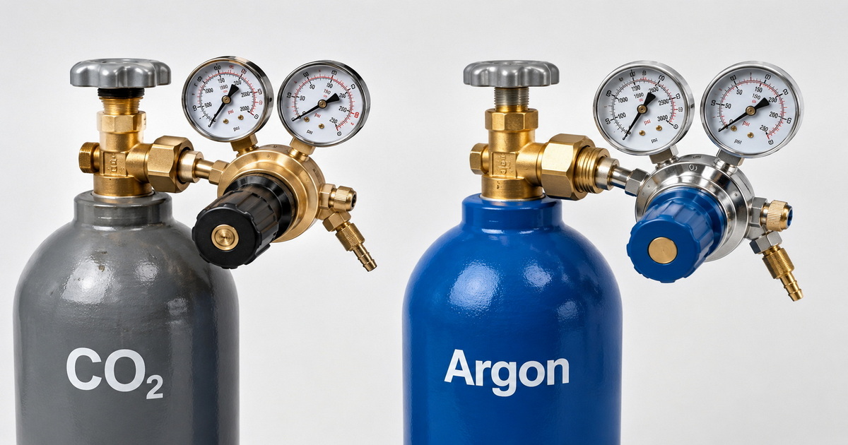
| Cylinder connection in North America | Commonly CGA-320 | Commonly CGA-580 |
| Gas behavior | Active shielding gas; supports deeper penetration and a more forceful arc | Inert shielding gas; stable arc, clean shielding, essential for most TIG applications |
| Flowmeter calibration | Must be rated for CO₂ | Must be rated for argon or the stated mixture |
| Typical buyer focus | Economy, carbon-steel penetration, robust MIG use | Arc control, cosmetic quality, TIG purity, multi-gas compatibility |
| Key risk | Using an incorrect inlet fitting or incompatible flow tube | Using an argon/CO₂ MIG mix for TIG welding |
CGA connection numbers exist to prevent improper regulator-to-cylinder connections. In North American practice, CGA-320 is commonly used for pure CO₂ cylinders, while CGA-580 is commonly used for argon, nitrogen, helium, and many argon-based welding mixtures. Never force, adapt, or modify a mismatched regulator connection.
Why Gas-Specific Calibration Matters
CO₂ and argon do not flow identically
A gas flowmeter is not just a transparent tube with a floating ball. It is a measuring device designed around gas-specific flow behavior. If a tube is labeled for argon, its scale is intended to indicate an argon flow rate under the regulator’s specified operating conditions. Using pure CO₂ through that same tube may produce a reading that does not equal the actual delivered flow.
For a welding distributor or OEM brand, this creates a practical specification rule:
– Select a CO₂-specific flowmeter regulator for pure CO₂ cylinders.
– Select an argon or argon/CO₂ flowmeter regulator for argon and approved mixed shielding gases.
– Clearly mark the gas type, inlet connection, outlet thread, flow range, and unit—such as L/min or CFH—on the product and packaging.
– Do not market a flow tube as universal unless its calibration and gas compatibility have been verified.
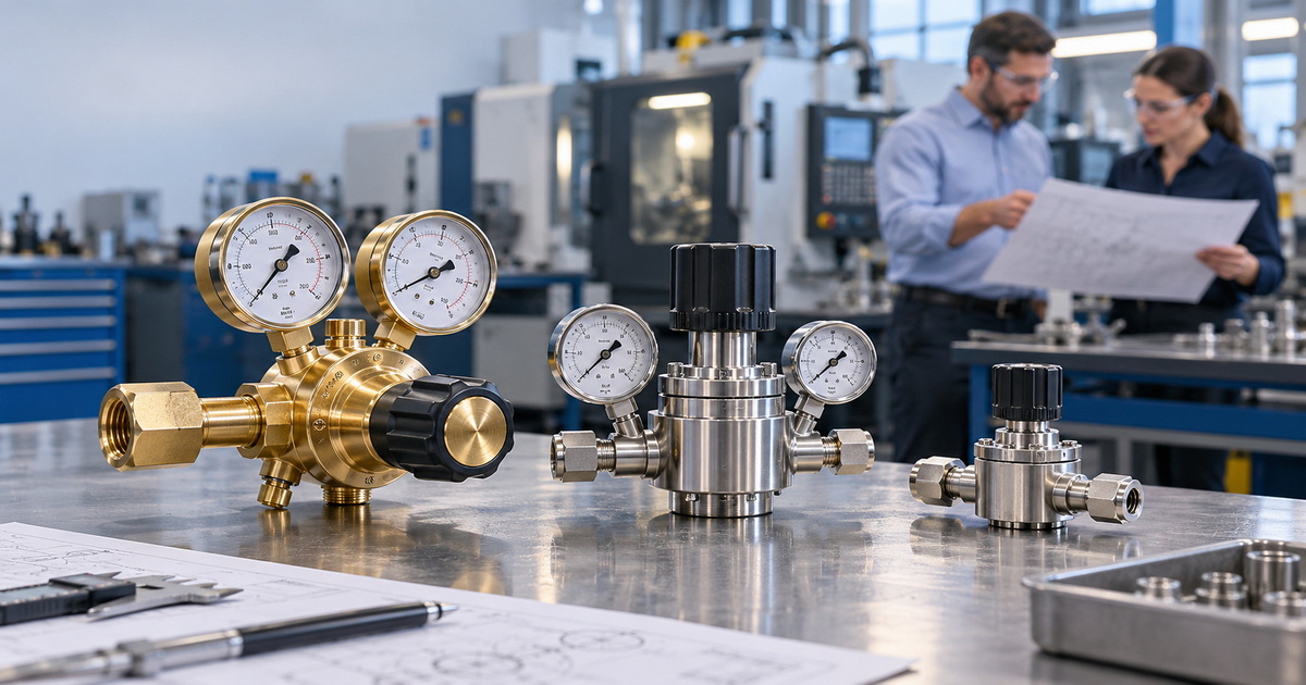
A professional product design should also use a stable brass regulator body, durable pressure gauges, a readable flow tube, protected gauge positioning, and reliable sealing components. These details matter because a small leak or unstable outlet pressure can lead to porosity, inconsistent bead appearance, and unnecessary gas consumption.
Regulator compatibility is as important as flow accuracy
An argon flowmeter regulator is often supplied with a CGA-580 inlet, while a pure CO₂ regulator commonly uses CGA-320. This difference is intentional. It helps reduce the risk of connecting equipment designed for one gas service to another cylinder type.
In addition, users should confirm:
– Cylinder-valve standard in their destination market.
– Required outlet thread and hose connection.
– Maximum inlet pressure.
– Outlet-pressure range.
– Flow range and unit of measurement.
– Gas compatibility of the flow tube, seals, and regulator.
– Certification and testing requirements for the local market.
CO₂ Flowmeter for MIG Welding
Where pure CO₂ performs well
Pure CO₂ is widely used for MIG/MAG welding of carbon steel because it is economical and can produce strong penetration. It is an active gas, meaning it participates in the arc environment rather than remaining fully inert.
In practical fabrication, pure CO₂ is often considered for:
– General carbon-steel fabrication.
– Farm and repair work.
– Structural components where appearance is less critical.
– High-volume welding where shielding-gas cost is important.
– Applications that benefit from stronger penetration.
However, welders should also expect trade-offs. Compared with argon-rich mixtures, pure CO₂ can create more spatter, a less stable arc in certain settings, and a rougher bead profile. These results depend on wire type, transfer mode, material thickness, machine settings, and operator technique.
Typical CO₂ MIG flow settings
There is no universal “correct” flow rate. The right setting depends on nozzle diameter, torch angle, joint design, transfer mode, ambient drafts, and the condition of the gas delivery system.
As a practical starting point, typical CO₂ flow for MIG welding is often in the 15–30 CFH range, then adjusted after checking shielding performance and weld appearance.
For indoor short-circuit MIG welding, Miller recommends approximately 25–35 CFH as a general flow range, while noting that the correct setting varies by process and conditions.
Use the following troubleshooting logic instead of continually increasing the flow:
| Welding symptom | Likely cause | Recommended action |
|---|---|---|
| Porosity in the bead | Draft, leak, contaminated base material, insufficient shielding | Check hoses and fittings with leak-detection solution; clean material; reduce air movement; adjust flow gradually |
| Excessive spatter | Gas choice, voltage/wire-feed mismatch, poor stickout | Verify welding parameters before assuming flow is the cause |
| Gas consumption is unusually high | Leak, over-flowing, damaged hose, loose fitting | Perform a complete gas-path inspection |
| No visible flow at torch | Closed valve, blocked line, damaged flowmeter, incorrect setup | Stop welding and inspect the system before restarting |
More gas is not always better. Excessive flow can create turbulence around the nozzle and draw surrounding air into the shielding zone. A better approach is to begin with a suitable baseline, inspect the gas system, and increase flow only when the weld environment truly requires it.
Argon Flowmeter for MIG and TIG Welding
Argon flowmeter for MIG welding
Argon-based gases are used in MIG welding for different reasons than pure CO₂. For mild steel, many operations choose an argon/CO₂ blend to achieve a smoother, more controllable arc and lower spatter than pure CO₂. Common blends vary by application, but 75% argon / 25% CO₂ and 80% argon / 20% CO₂ are widely recognized choices for general carbon-steel MIG welding.
For aluminum MIG welding, pure argon is commonly used because it provides an inert shielding environment suitable for aluminum welding. Flow requirements may be higher than for standard indoor steel MIG work because nozzle design, wire feed, transfer characteristics, and application conditions differ.
A flowmeter regulator designed for argon/CO₂ shielding gas is specifically available from major equipment suppliers. For example, Lincoln Electric identifies its Model 355 kit as a flowmeter regulator designed to control argon/carbon dioxide shielding gases.
Argon flowmeter for TIG welding
For most TIG welding, pure argon is the standard starting point. TIG welding depends on a clean, stable shielding envelope around the tungsten electrode and molten weld pool. Contamination can quickly cause tungsten discoloration, unstable arc behavior, oxidation, and poor bead appearance.
CO₂ and oxygen-containing MIG mixtures are generally unsuitable for normal TIG welding because they can oxidize and contaminate the tungsten electrode. Industry guidance commonly recommends argon, argon/helium blends, or helium for GTAW/TIG rather than CO₂-containing gases.
Typical TIG flow rates often fall between 10 and 35 CFH, with exact settings depending on cup size, tungsten size, joint geometry, post-flow needs, material, and surrounding air movement.
For many indoor TIG jobs, start at a moderate rate, inspect the weld zone, and optimize based on results. A large cup, gas lens, open joint, or back-purge requirement may need a different setup than a standard fillet weld.
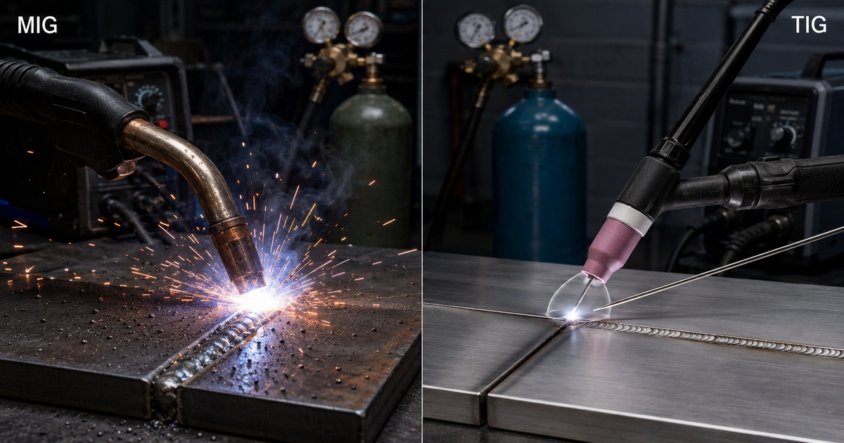
MIG vs. TIG: Which Flowmeter Should You Specify?
The best flowmeter depends on the gas and process, not simply on whether the customer says “MIG regulator” or “TIG regulator.”
| Application | Recommended gas approach | Flowmeter/regulator specification |
|---|---|---|
| Carbon-steel MIG with pure CO₂ | Pure CO₂ | CO₂-rated flowmeter regulator; correct CO₂ cylinder connection |
| Carbon-steel MIG with 75/25 or similar blend | Argon/CO₂ mixture | Argon/CO₂-rated flowmeter regulator; correct mixture-cylinder connection |
| Aluminum MIG | Usually pure argon | Argon-rated flowmeter regulator |
| Stainless TIG | Usually pure argon; specialized blends only when process-qualified | Argon-rated flowmeter regulator; optional dual-flow configuration for purge applications |
| Carbon-steel TIG | Usually pure argon | Argon-rated flowmeter regulator |
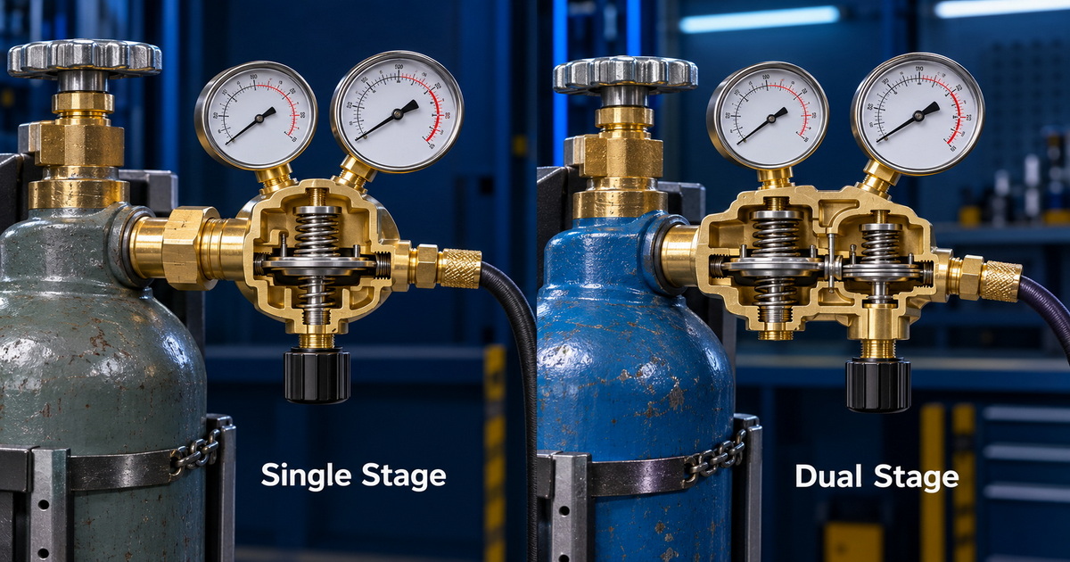
| Pipe TIG with back purge | Argon for torch and purge where procedure requires it | Dual-stage or dual-flowmeter configuration where independent flows are needed |
For purge-sensitive welding, dual-flowmeter designs can be valuable. Lincoln Electric describes a dual-flowmeter regulator that provides two independently adjustable flows from one gas source for applications such as back purging and trail purging.
Practical Setup Checklist for Welders
Before welding, use this five-step routine:
1. Identify the shielding gas. Confirm whether the cylinder contains pure CO₂, pure argon, or an argon-based mixture.
2. Match the inlet connection. Never force a regulator onto an incompatible cylinder valve.
3. Confirm flowmeter calibration. Read the label and ensure the flow tube is approved for the gas being used.
4. Leak-test the gas path. Use an approved leak-detection solution on fittings, hose ends, and regulator connections.
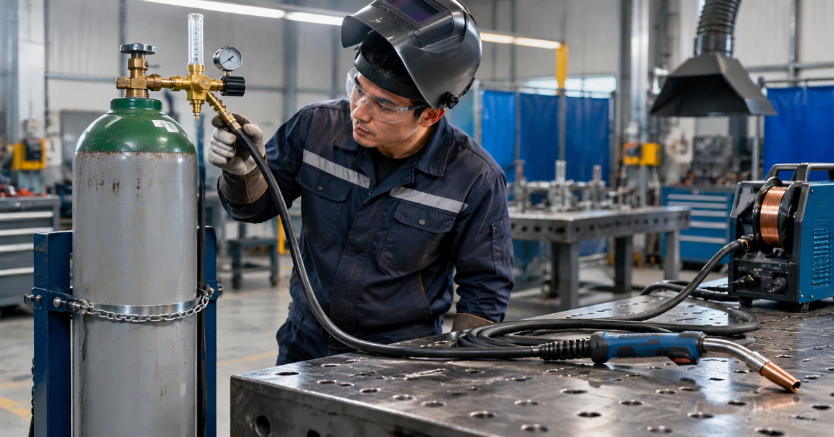
5. Set flow while gas is flowing. Trigger the torch or use a gas-purge function, then adjust the flowmeter ball to the required range.
Always secure cylinders upright and use a suitable regulator. Safety guidance also warns against using damaged equipment, using a flowmeter with gas other than the specified type, or connecting a flowmeter inlet to a pressure source beyond its rated limit.
How OEM Buyers Can Evaluate a Welding Gas Regulator Supplier
For overseas brands, wholesalers, and industrial distributors, the most useful purchasing decision is not “CO₂ vs. argon” alone. It is whether the supplier can build the correct configuration for the target market and application.
Evaluate these factors:
– Material quality: Brass bodies and durable internal components for stable gas control.
– Gas-specific design: Clear distinction between CO₂, argon, oxygen, acetylene, propane, nitrogen, and mixed-gas models.
– Flow accuracy: Suitable flow-tube calibration and readable scale markings.
– Connection customization: CGA, DIN, BS, JIS, or customer-specified inlet configurations.
– Pressure-control stability: Single-stage or dual-stage design based on pressure-stability requirements.
– Quality inspection: Leakage testing, pressure testing, gauge inspection, and final functional testing.
– Brand customization: OEM logo, packaging, color coding, manuals, labels, and private-label support.
– Documentation: Product specifications, gas-compatibility instructions, batch traceability, and relevant compliance documentation.
For a branded product line, clear labeling is a conversion and safety advantage. It helps distributors avoid unnecessary returns, improves end-user confidence, and makes online product comparison easier.
Final Recommendation
Use a CO₂ flowmeter regulator for pure CO₂ MIG/MAG welding and an argon-rated flowmeter regulator for TIG welding, aluminum MIG, and approved argon-based MIG mixtures. Do not assume that the same flow scale, cylinder fitting, or regulator configuration is suitable for every gas.
If you are sourcing welding gas regulators for your own brand, specify the gas type, cylinder connection, flow unit, flow range, outlet configuration, target market, and application before production. A correctly engineered regulator helps your customers achieve consistent shielding, control gas costs, and weld with greater confidence.
Looking for OEM or ODM CO₂ and argon flowmeter regulators? Contact our team with your target market, gas type, required cylinder connection, flow range, and branding requirements. We can help configure precision brass gas regulators and industrial gas-control solutions for your welding-equipment product line.
FAQ
1. Can I use an argon flowmeter for pure CO₂?
Not unless the product manufacturer explicitly states that the flowmeter is calibrated and approved for CO₂. Gas-specific calibration affects reading accuracy, and the cylinder inlet connection may also differ.
2. Is pure CO₂ suitable for TIG welding?
Generally, no. Standard TIG welding normally uses pure argon, argon/helium blends, or helium. CO₂ can oxidize and contaminate the tungsten electrode and weld zone.
3. What is the best gas flow rate for MIG welding?
It depends on the process and environment. For indoor MIG short-circuit welding, a common reference range is 25–35 CFH, but nozzle size, drafts, leaks, gas type, and welding parameters must be considered.
4. What is the normal argon flow rate for TIG welding?
A common TIG range is 10–35 CFH. Start with the welding procedure, then adjust for cup size, joint shape, post-flow, and air movement.
5. Why does my weld have porosity even when the flowmeter is set high?
High flow does not guarantee effective shielding. Check for leaks, drafts, dirty material, damaged consumables, incorrect torch angle, insufficient gas coverage, or turbulence caused by excessive flow.
6. What is the difference between a gas regulator and a flowmeter?
A regulator reduces cylinder pressure to a usable controlled pressure. A flowmeter measures and adjusts the volume of gas delivered over time. Many welding products combine both functions in one regulator-flowmeter assembly.
7. Do I need a dual-flowmeter regulator for TIG welding?
Not for every job. It becomes useful when the torch and a separate purge line need independently controlled gas flow, such as in stainless-steel pipe welding, back purging, or trail shielding.
References
1. Miller Welding. “[What Type of Gas Is Best for MIG Welding in DIY Applications?]” Accessed August 16, 2026.
2. Miller Welding. “[Best Practices for Proper Shielding Gas in TIG Welding]” Accessed August 16, 2026.
3. Lincoln Electric. “[Model 355-2Ar/CO₂-58010 Flowmeter Regulator Shielding Gas]” Accessed August 16, 2026.
4. Lincoln Electric. “[Model 356-Ar/He-580 Dual Flowmeter Regulator]” Accessed August 16, 2026.
5. American Welding Society Forum. “[Argon, Helium, and CO₂…?]” Accessed August 16, 2026.
6. Weld Support Parts. “[Welding Gas Reference Guide: CGA Numbers & Uses]” Accessed August 16, 2026.
7. Arc-Zone. “[Safety Rules for Gases: Flow Meter Safety Rules]” Accessed August 16, 2026.
8. TWI. “[Health Risks From Fume and Gases During Welding]” Accessed August 16, 2026.
Hot Tags: CO₂ Flowmeter Regulator, Argon Flowmeter Regulator, MIG Welding Gas Regulator, TIG Welding Argon Regulator, Welding Gas Flowmeter, CO₂ Welding Regulator, Argon CO₂ Flowmeter Regulator, Dual Stage Gas Regulator, Industrial Gas Pressure Regulator, OEM Welding Gas Regulator