Content Menu
● What Does Unstable Welding Gas Flow Look Like?
● Why Welding Gas Pressure and Flow Are Different
>> Understand Your Flow-Control Device
● Seven Common Causes of Unstable Welding Gas Flow
>> 1. Leaks in Hoses, Fittings, or Torch Connections
>> 2. Restricted Hoses and Blocked Gas Passages
>> 3. Incorrect Flowmeter Setup
>> 4. Regulator Instability or Internal Wear
>> 5. CO₂ Regulator Cooling and Freeze-Up
>> 7. Drafts and Excessive Shielding Gas Flow
● How Much Shielding Gas Flow Should You Use?
● A Safe Troubleshooting Sequence for Unstable Welding Gas Flow
>> Step 1: Make the Setup Safe
>> Step 3: Verify Supply and Instrument Setup
>> Step 4: Inspect and Leak-Test the Delivery Path
>> Step 5: Compare Upstream Indication With Torch Delivery
>> Step 6: Repeat Under Representative Conditions
● Use Timing to Locate the Fault
● When Should You Choose a Dual-Stage Gas Regulator?
● OEM and ODM Purchasing: Specify Stability, Not Appearance
● Get a Gas Regulator Matched to Your Welding System
>> 1.Why Does My Welding Gas Flow Surge When I Pull the Trigger?
>> 2.Why Is My Flowmeter Steady but My Weld Still Porous?
>> 3.Can Too Much Shielding Gas Cause Problems?
>> 4.Do I Always Need a Heated CO₂ Regulator?
>> 5.Will a Dual-Stage Regulator Solve Unstable Welding Gas Flow?
>> 6.Can I Use an Oxygen Regulator for Argon or CO₂?
Unstable welding gas flow usually comes from leaks, restrictions, incorrect flowmeter settings, regulator problems, CO₂ cooling, or pressure building inside the hose between welds. Sometimes, the flow itself is steady, but drafts or a blocked nozzle disrupt shielding at the weld.
The most useful starting point is diagnosis, not a higher gas setting. Increasing flow without finding the cause can waste gas and create turbulence that draws air into the shielding envelope.
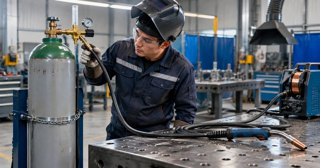
What Does Unstable Welding Gas Flow Look Like?
Identify when the problem happens before replacing components.
| Symptom | Possible cause | First check |
|---|---|---|
| A strong burst at every start | Pressurized gas stored in the hose | Hose length and surge-control configuration |
| Flow falls during continuous welding | Restriction, inadequate supply, or CO₂ cooling | Supply capacity, hose condition, and regulator |
| Flowmeter float moves irregularly | Changing pressure, restriction, or sticking float | Meter orientation and operating conditions |
| Regulator reading looks steady, but shielding is poor | Downstream leak, nozzle blockage, or drafts | Torch-end delivery and work area |
| Delivery pressure keeps rising while gas is off | Possible regulator seat leakage | Stop use and arrange qualified inspection |
| Problems appear when another station starts | Shared supply pressure loss | Manifold capacity under simultaneous demand |
Why Welding Gas Pressure and Flow Are Different
Pressure describes the force driving gas through the system. Flow describes the volume delivered over time.
A pressure gauge normally reads psi or bar. A shielding gas flow indicator normally reads cubic feet per hour, abbreviated CFH, or liters per minute.
A steady pressure reading does not guarantee adequate flow at the torch. A restricted hose can maintain upstream pressure while limiting downstream delivery.
Understand Your Flow-Control Device
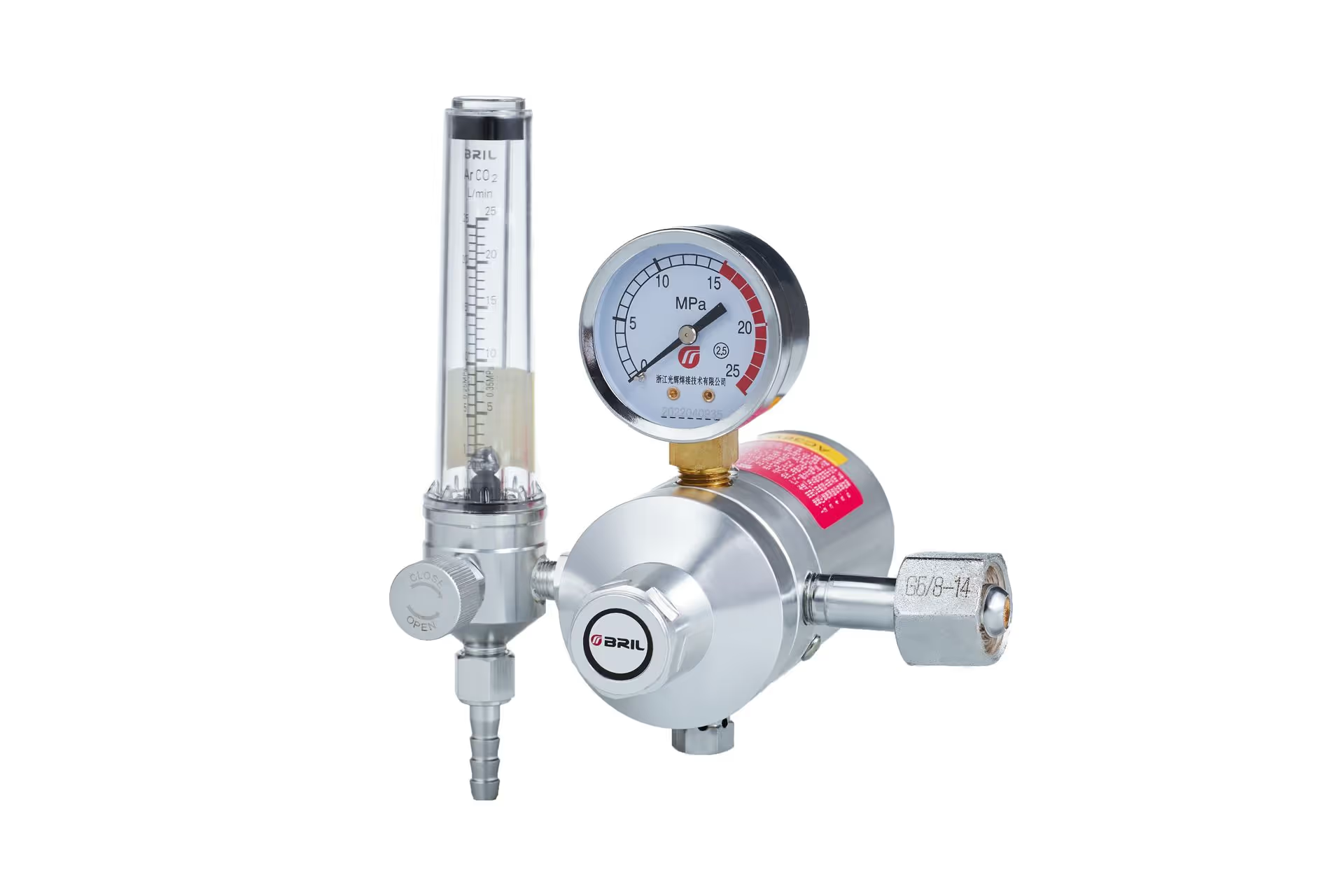
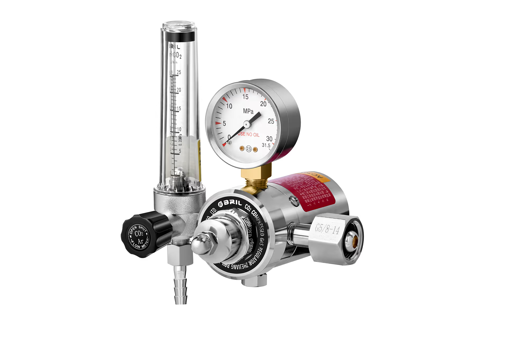
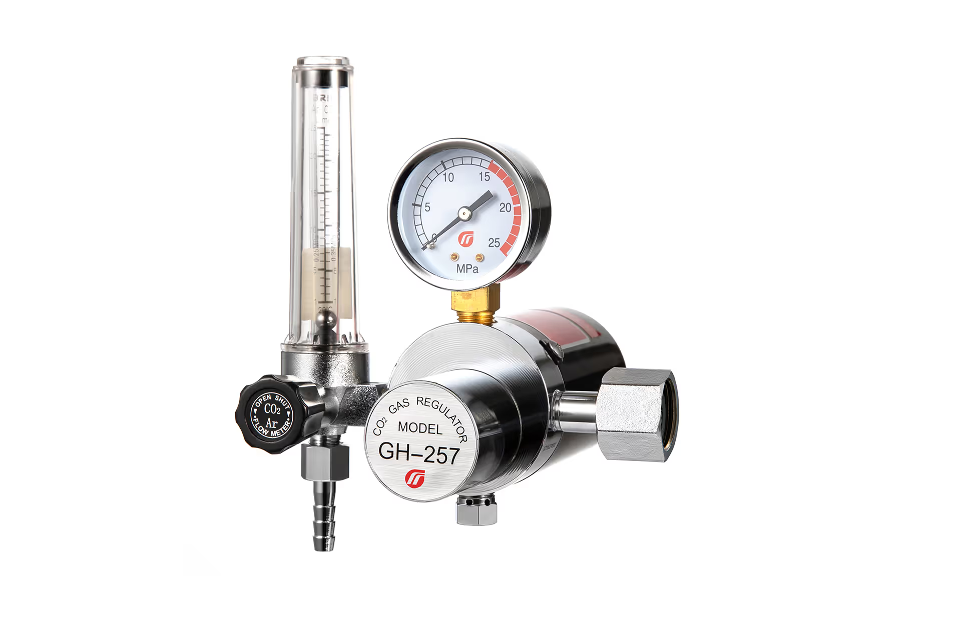
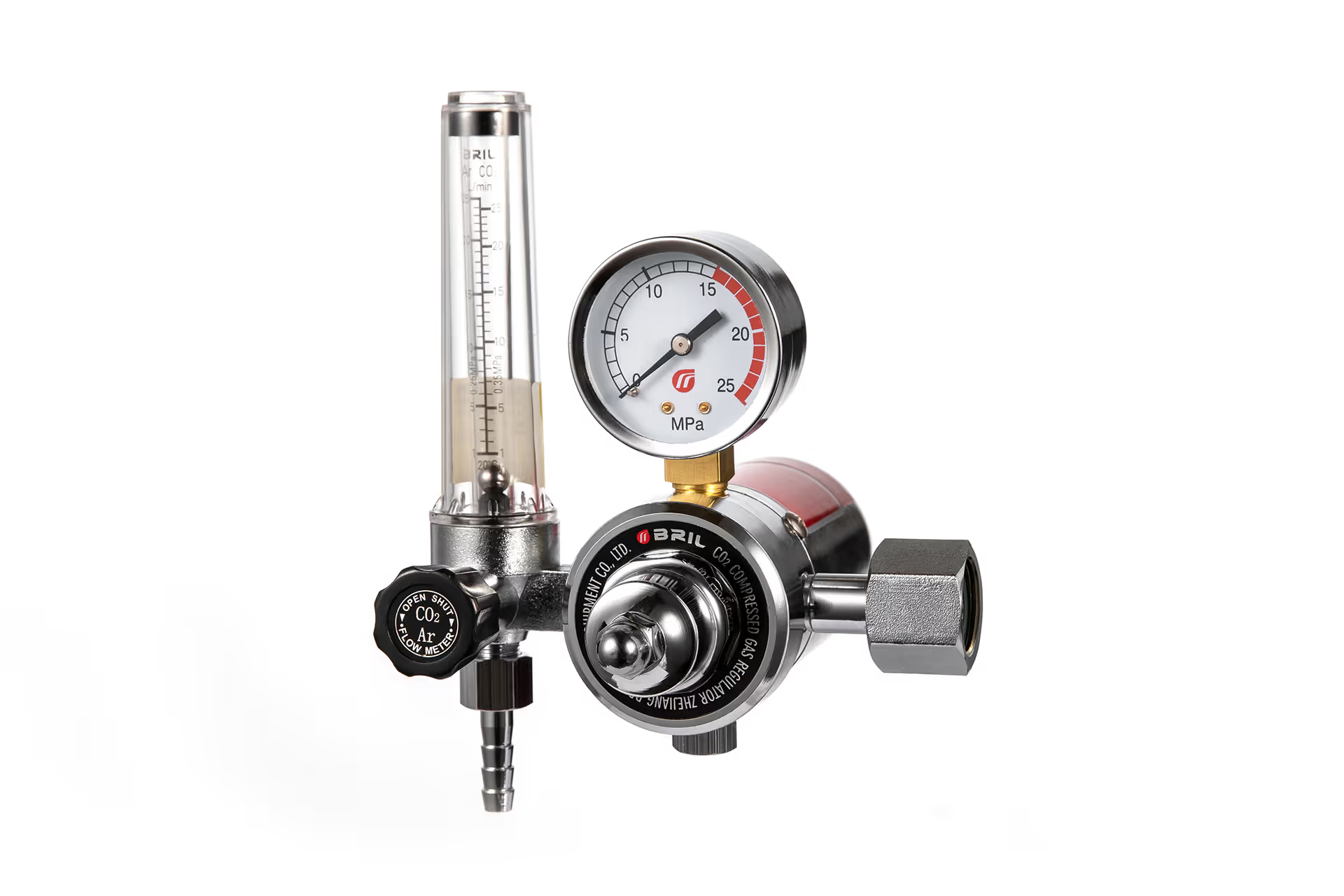
A floating-ball flowmeter indicates flow under specified calibration conditions. A dial-style flowgauge generally infers flow from pressure through a defined restriction.
Neither should be treated as universally interchangeable.
Check:
– The gas or mixture identified on the scale.
– The required operating pressure.
– The specified installation orientation.
– Whether the downstream restriction matches the design.
– The manufacturer’s instructions for reading the float.
Set flow while gas is moving through the actual delivery circuit. Use the machine’s purge function where available, following its instructions.
Seven Common Causes of Unstable Welding Gas Flow
1. Leaks in Hoses, Fittings, or Torch Connections
A regulator-mounted indicator cannot tell you how much gas actually reaches the weld. Gas may escape through loose connections, damaged hoses, worn seals, or poorly seated torch fittings.
Inspect the complete route from cylinder to torch.
Use a leak-detection product approved for the gas and equipment. Never check with a flame, and never tighten or disconnect a pressurized joint.
If a leak cannot be corrected through an authorized external connection procedure, isolate the supply and arrange service.
2. Restricted Hoses and Blocked Gas Passages
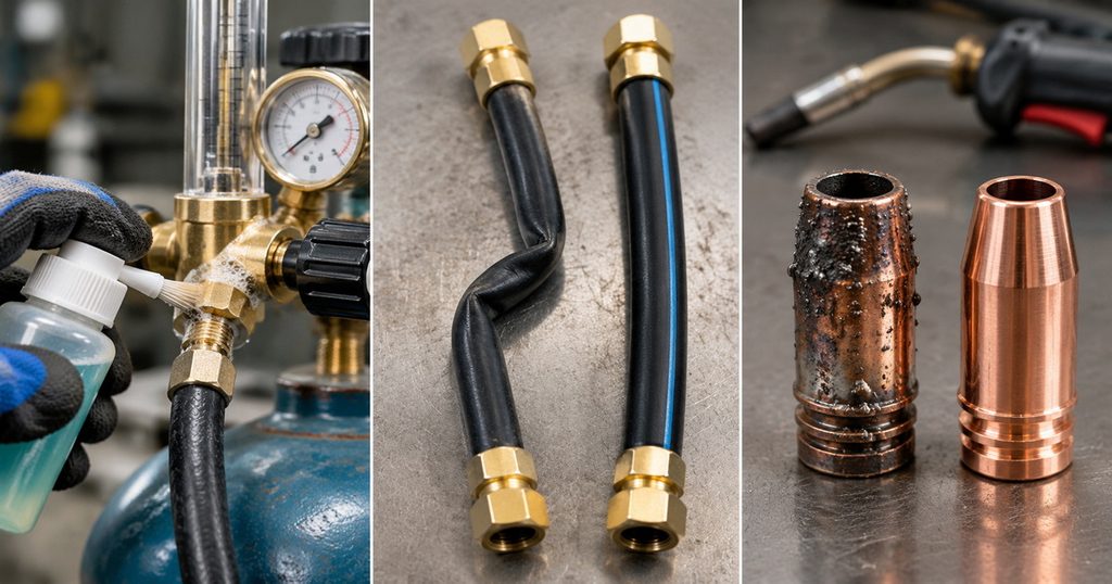
Kinked hoses, undersized lines, damaged connectors, and spatter-filled nozzles can reduce delivery.
Check the hose along its entire length. Pay particular attention to areas trapped beneath equipment or bent sharply around a trolley.
At the torch, inspect:
– Nozzle openings.
– Gas diffuser passages.
– Seals and insulating components.
– Torch-to-feeder connections.
Clean or replace components according to the torch manufacturer’s instructions. Do not enlarge passages to increase flow.
3. Incorrect Flowmeter Setup
A tilted variable-area flowmeter, unsuitable gas scale, or incorrect inlet pressure can produce misleading readings.
Flowmeter calibration depends on gas properties and operating conditions. An argon scale should not automatically be treated as accurate for CO₂, helium, or every mixed gas.
Also check the units. A setting of 15 CFH is very different from 15 L/min.
Before adjusting anything, confirm that the instrument matches the gas, pressure, and intended application.
4. Regulator Instability or Internal Wear
A regulator reduces cylinder pressure to a usable delivery pressure. Its behavior depends on design, condition, inlet pressure, and demand.
Three effects deserve separate attention:
– Droop: delivery pressure falls as flow demand increases.
– Supply-pressure effect: delivery pressure changes as cylinder pressure changes.
– Creep: delivery pressure continues rising after downstream flow stops.
Creep is not something to manage by repeatedly turning the adjustment knob. After normal settling, continued pressure rise requires qualified evaluation.
Do not dismantle a regulator unless you are trained and authorized to service that model.
5. CO₂ Regulator Cooling and Freeze-Up
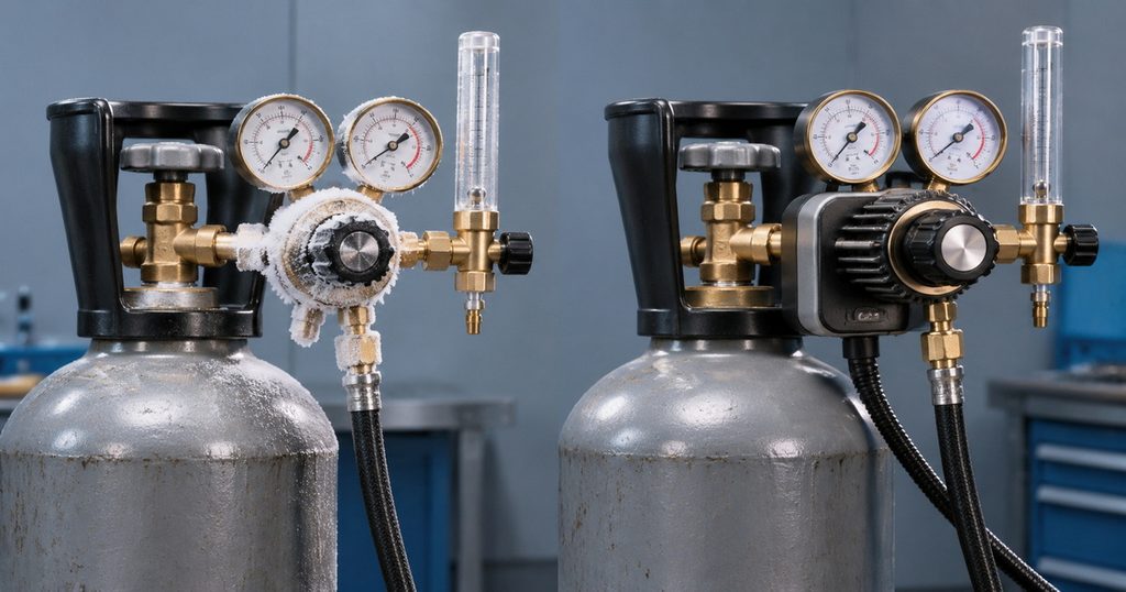
CO₂ behaves differently from compressed argon. Under certain pressure and temperature conditions, dry ice can form and restrict passages inside the regulator.
Possible signs include falling flow during sustained operation and recovery after an idle period. External frost alone, however, does not prove an internal blockage.
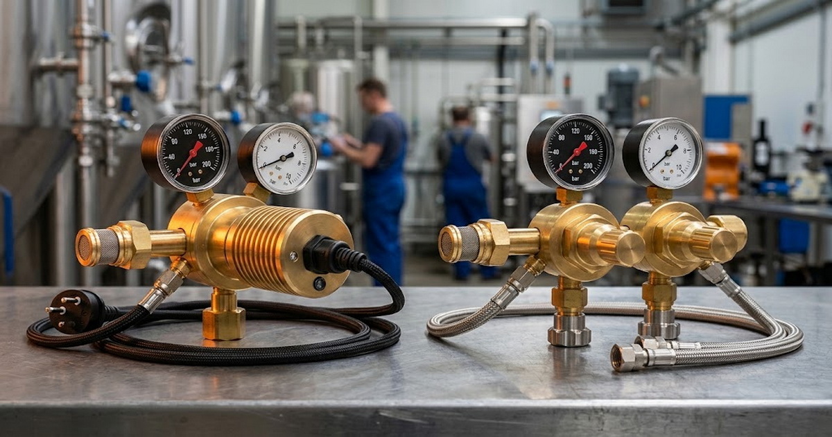
A correctly selected CO₂ heated regulator can help address regulator freeze-up. Selection must consider continuous flow, ambient temperature, supply conditions, and electrical requirements.
A heater cannot compensate for inadequate cylinder vaporization capacity or an unsuitable supply arrangement. Never heat a cylinder or regulator with a flame or improvised heater.
6. Gas Surge at Arc Start
When a welding solenoid closes, pressure can build in the hose upstream of it. On reopening, the stored gas may discharge as a brief burst before settling.
This explains why a system can surge at every start yet appear stable during a long weld.
Longer hoses and higher stored pressure can increase the amount released. Suitable low-pressure or surge-control equipment may help, provided it remains compatible with the machine’s required supply conditions.
7. Drafts and Excessive Shielding Gas Flow
Sometimes, the gas supply is stable but shielding is not.
Fans, open doors, extraction arrangements, and cross-drafts can move the shielding envelope away from the weld pool. Excessive flow can also create turbulence and entrain air.
Before increasing the setting, inspect nozzle coverage, torch position, and airflow around the joint. Use suitable screening without compromising required fume extraction or ventilation.
How Much Shielding Gas Flow Should You Use?
There is no universal setting for every MIG or TIG application.
As published examples, Miller recommends 15–20 CFH for common TIG troubleshooting and 25–35 CFH for MIG short-circuit welding in its gas-selection guidance.
These figures are starting references, not substitutes for your welding procedure or equipment instructions. Appropriate flow depends on:
– Welding process and transfer mode.
– Gas composition.
– Nozzle or cup size.
– Joint geometry and access.
– Torch position and working distance.
– Surrounding airflow.
The practical goal is sufficient, repeatable shielding—not the highest meter reading. If increasing flow makes porosity worse, investigate turbulence and leaks rather than continuing upward.
A Safe Troubleshooting Sequence for Unstable Welding Gas Flow
Step 1: Make the Setup Safe
Secure the cylinder upright and ensure suitable ventilation. Confirm that the regulator, hose, connections, and gas are compatible.
If you hear uncontrolled leakage, see damaged equipment, or observe abnormal pressure rise, stop and isolate the system according to site procedures.
Step 2: Record the Pattern
Note whether instability occurs at startup, during continuous welding, near cylinder depletion, or when another station operates.
Record gas type, regulator model, flow setting, hose length, and ambient conditions. This makes supplier support much more useful.
Step 3: Verify Supply and Instrument Setup
Check supply availability and the regulator’s operating range.
For CO₂ cylinders containing liquid, pressure depends strongly on temperature and is not a reliable linear contents indicator. Follow the supplier’s method for assessing remaining contents, commonly by weight.
Step 4: Inspect and Leak-Test the Delivery Path
Check accessible fittings, hoses, seals, and torch connections using approved procedures.
Depressurize before correcting connections or replacing components. Retest after reassembly.
Step 5: Compare Upstream Indication With Torch Delivery
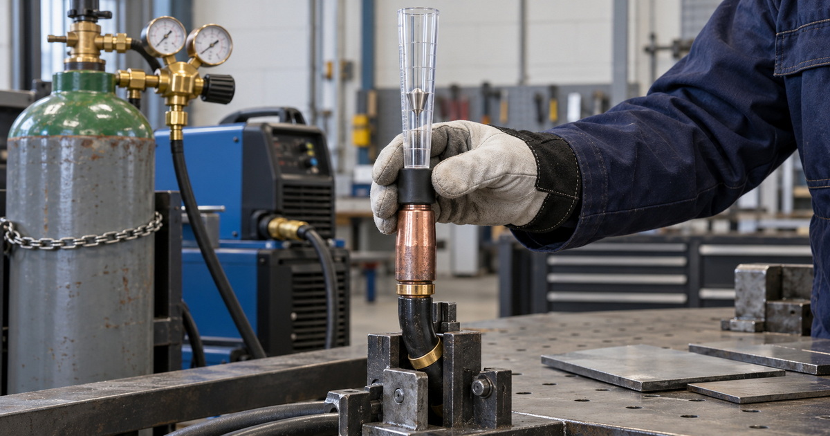
Where appropriate, use a compatible torch-end flow checker while operating the purge function.
A meaningful difference between upstream indication and torch delivery points toward a downstream leak, restriction, or measurement mismatch.
A torch-end checker is diagnostic; it does not replace calibrated equipment where formal verification is required.
Step 6: Repeat Under Representative Conditions
Test several starts and a sustained purge within equipment limits. Where relevant, check simultaneous demand from other stations.
Change one variable at a time so the improvement can be traced to a specific correction.
Use Timing to Locate the Fault
Timing often reveals more than a single gauge reading.
Consider this illustrative diagnostic comparison—not a reported customer case:
– An immediate burst followed by normal flow suggests stored hose pressure.
– A gradual decline during continuous CO₂ use suggests a thermal or supply-capacity issue.
– A sudden drop when another welder starts suggests shared-system pressure loss.
– Stable delivery with intermittent porosity suggests checking shielding coverage, contamination, and welding technique.
For production troubleshooting, record startup behavior separately from steady-state flow. A satisfactory average reading can hide an excessive initial surge.
When Should You Choose a Dual-Stage Gas Regulator?
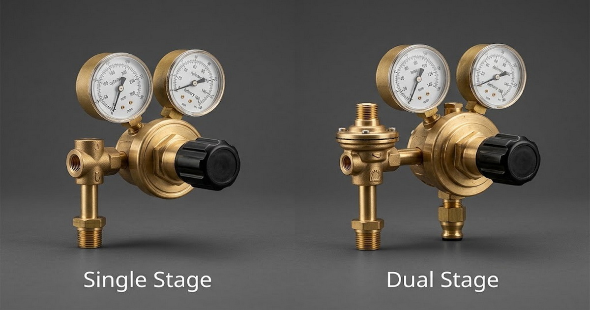
A dual-stage regulator reduces pressure in two successive steps. It is useful when more consistent delivery pressure is needed as cylinder pressure changes.
Consider it for repeatable production, longer operating periods, or applications sensitive to pressure variation.
However, dual-stage construction does not repair leaks, clear a blocked nozzle, eliminate drafts, or automatically prevent CO₂ freeze-up.
Also, two gauges do not mean two stages. One gauge may show cylinder pressure and the other delivery pressure on a single-stage regulator.
Specify the required performance first, then select the design.
OEM and ODM Purchasing: Specify Stability, Not Appearance
For overseas brands, wholesalers, distributors, and equipment manufacturers, an attractive brass body is only part of the specification.
Precision machining, suitable materials, clean assembly, and inspection support reliability. Buyers should nevertheless request measurable acceptance criteria.
| Purchasing requirement | What to define |
|---|---|
| Gas compatibility | Gas, mixture, wetted materials, and seals |
| Supply conditions | Maximum and minimum inlet pressure |
| Operating demand | Flow range and continuous duty |
| Pressure stability | Permitted variation across demand and inlet conditions |
| Shutoff behavior | Lock-up and creep acceptance criteria |
| Measurement | Gas scale, units, and calibration conditions |
| Market compatibility | Cylinder connection and applicable product requirements |
| Documentation | Instructions, inspection records, and traceability |
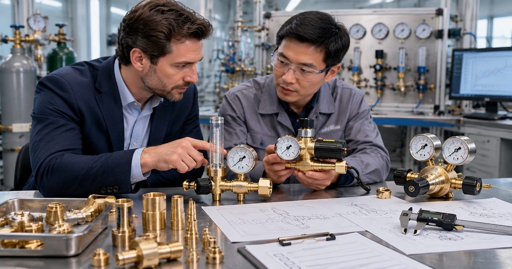
For heated CO₂ regulators, also define voltage, frequency, power, temperature protection, and intended operating conditions.
Ask which standards apply to the exact model and configuration. Do not assume a certification covers every product variation.
Get a Gas Regulator Matched to Your Welding System
Reliable shielding starts with a correctly specified supply system, not repeated adjustments.
For OEM and ODM inquiries, send us your gas type, inlet-pressure range, target flow, duty cycle, cylinder connection, destination market, and any observed instability. Our manufacturing focus combines precision production, brass construction, quality inspection, and customized gas-control solutions.
Whether you need an argon regulator, CO₂ heated regulator, or dual-stage configuration, use an application-based specification and agreed inspection criteria to guide selection.
Frequently Asked Questions
1.Why Does My Welding Gas Flow Surge When I Pull the Trigger?
Gas stored under pressure between the regulator and solenoid can escape rapidly when the valve opens. Check hose configuration and compatible surge-control options.
2.Why Is My Flowmeter Steady but My Weld Still Porous?
Gas may be leaking downstream, the nozzle may be obstructed, or drafts may disrupt coverage. Contamination and unsuitable welding parameters can also cause porosity.
3.Can Too Much Shielding Gas Cause Problems?
Yes. Excessive flow can create turbulence that draws surrounding air into the shielding envelope. More flow does not automatically mean better protection.
4.Do I Always Need a Heated CO₂ Regulator?
No. The need depends on flow demand, duty cycle, temperature, and supply conditions. Select heating equipment for the actual application rather than assuming all CO₂ systems require it.
5.Will a Dual-Stage Regulator Solve Unstable Welding Gas Flow?
It can improve delivery-pressure consistency as cylinder pressure changes. It will not correct downstream leaks, blocked passages, drafts, or every thermal problem.
6.Can I Use an Oxygen Regulator for Argon or CO₂?
Do not substitute regulators based on appearance or a fitting that seems compatible. Use equipment specifically approved for the gas, pressure, connection, and service conditions.
References
1. Miller Electric — “Common TIG Welding Problems.” Practical guidance on shielding gas selection, the 15–20 CFH TIG reference range, excessive-flow turbulence, and leak checks. [millerwelds]
2. Miller Electric — “What Type of Gas Is Best for MIG Welding in DIY Applications?” Gas-selection guidance, including the 25–35 CFH short-circuit MIG reference range and the consequences of insufficient or excessive flow. [millerwelds]
3. TWI — “Porosity in Welding: Defects / Imperfections in Welds.” Technical explanation of porosity, air entrainment, gas-line leaks, excessive flow, drafts, and turbulence. [twi-global]
4. Miller Electric — “Tips for Troubleshooting Common MIG Weld Defects.” Guidance on hoses, gun leaks, nozzle cleanliness, shielding coverage, and drafts. [prod.millerwelds]
5. Harris Products Group — “CO₂ Freeze Up: Why It Happens, What You Can Do.” Explanation of dry-ice formation and restricted regulator flow. [harrisproductsgroup]
6. Harris Products Group — “Carbon Dioxide Regulator Freezing.” Technical discussion of heated regulators as a response to CO₂ freeze-up. [harrisproductsgroup]
7. Harris Products Group — “Lessons Learned in Reducing Shielding Gas Costs.” Explanation of idle hose-pressure buildup and startup gas surge. [harrisproductsgroup]
8. Harris Products Group — “Shielding Gas.” Comparison of flow-control principles, including fixed-pressure/variable-orifice and variable-pressure/fixed-orifice devices. [harrisproductsgroup]
9. Harris Products Group — “Gas Regulation.” Selection guidance for two-stage regulators where consistent delivery pressure over cylinder life is important. [harrisproductsgroup]
10. Victor / ESAB — “Victor Gas Equipment Safety: Equipment Setup.” Guidance on gas-specific equipment ratings, compatible connections, and safe installation. [esab]
11. Victor — “EDGE Series 2.0 Regulators Instruction Manual.” Manufacturer procedures concerning regulator inspection, leakage, and pressure creep; service testing should be performed only by qualified personnel. [pdiimages.praxair]
Hot Tags: Welding Gas Regulator, Shielding Gas Regulator, Welding Gas Flowmeter, CO₂ Gas Regulator, Heated CO₂ Regulator, Argon Gas Regulator, Dual Stage Gas Regulator, Industrial Gas Pressure Regulator, OEM Gas Regulator Manufacturer, Welding Gas Regulator Supplier