Content Menu
● How an Argon Regulator with Flowmeter Works
>> Pressure Regulation Is Not Flow Measurement
>> Flowmeter Regulators and Flow-Gauge Regulators
● Why Shielding Gas Control Matters in TIG Welding
>> More Gas Does Not Always Improve Protection
● Recommended Argon Flow Rate for TIG Welding
>> Set Flow While Gas Is Actually Moving
>> Treat Preflow and Postflow Separately
● How to Choose an Argon Flowmeter Regulator
>> Confirm Gas Service and Calibration
>> Match Cylinder and Hose Connections
>> Choose a Readable, Useful Flow Range
>> Evaluate Brass Construction Beyond Appearance
● Single-Stage vs. Dual-Stage Argon Regulators
>> When Dual-Stage Control Adds Value
● Step-by-Step Setup for an Argon Regulator with Flowmeter
● Troubleshooting Poor Shielding and Unstable Flow
>> Check the System Before Blaming One Component
● A Practical Acceptance Plan for Distributors and OEM Buyers
>> Verify Performance Across Operating Conditions
● OEM and ODM Argon Regulator Manufacturing
>> Define the Specification Before Customizing Appearance
● Request a Specification-Based Quotation
>> 1.What Is the Best Argon Flow Rate for TIG Welding?
>> 2.Can I Use an Argon/CO₂ Welding Mix for TIG?
>> 3.Why Does Increasing Gas Flow Make My Weld Worse?
>> 4.Does a Dual-Stage Regulator Guarantee Constant Flow?
>> 5.Can One Regulator Be Used for Different Industrial Gases?
>> 6.What Information Should I Send for an OEM Quotation?
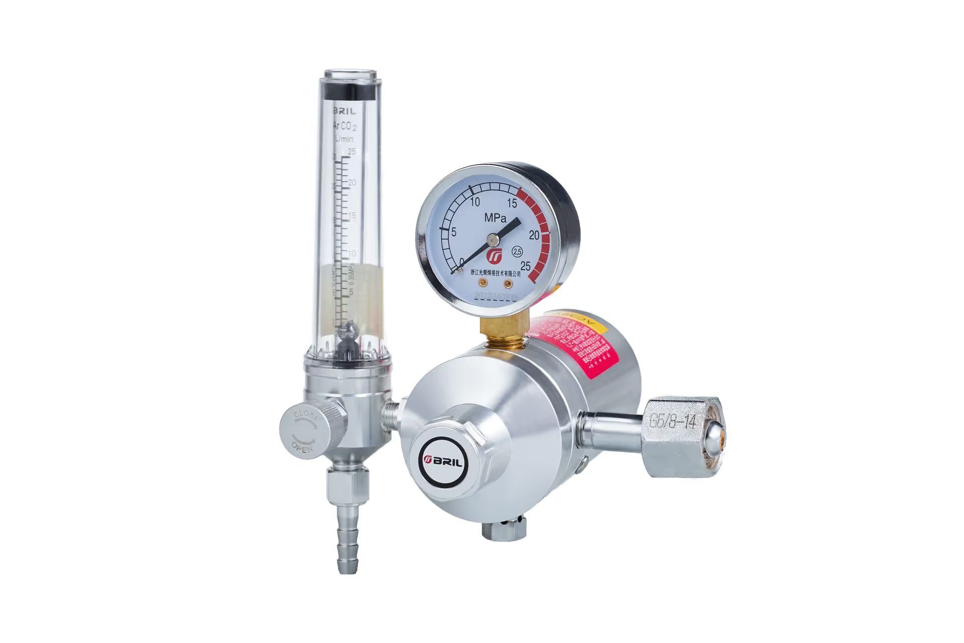
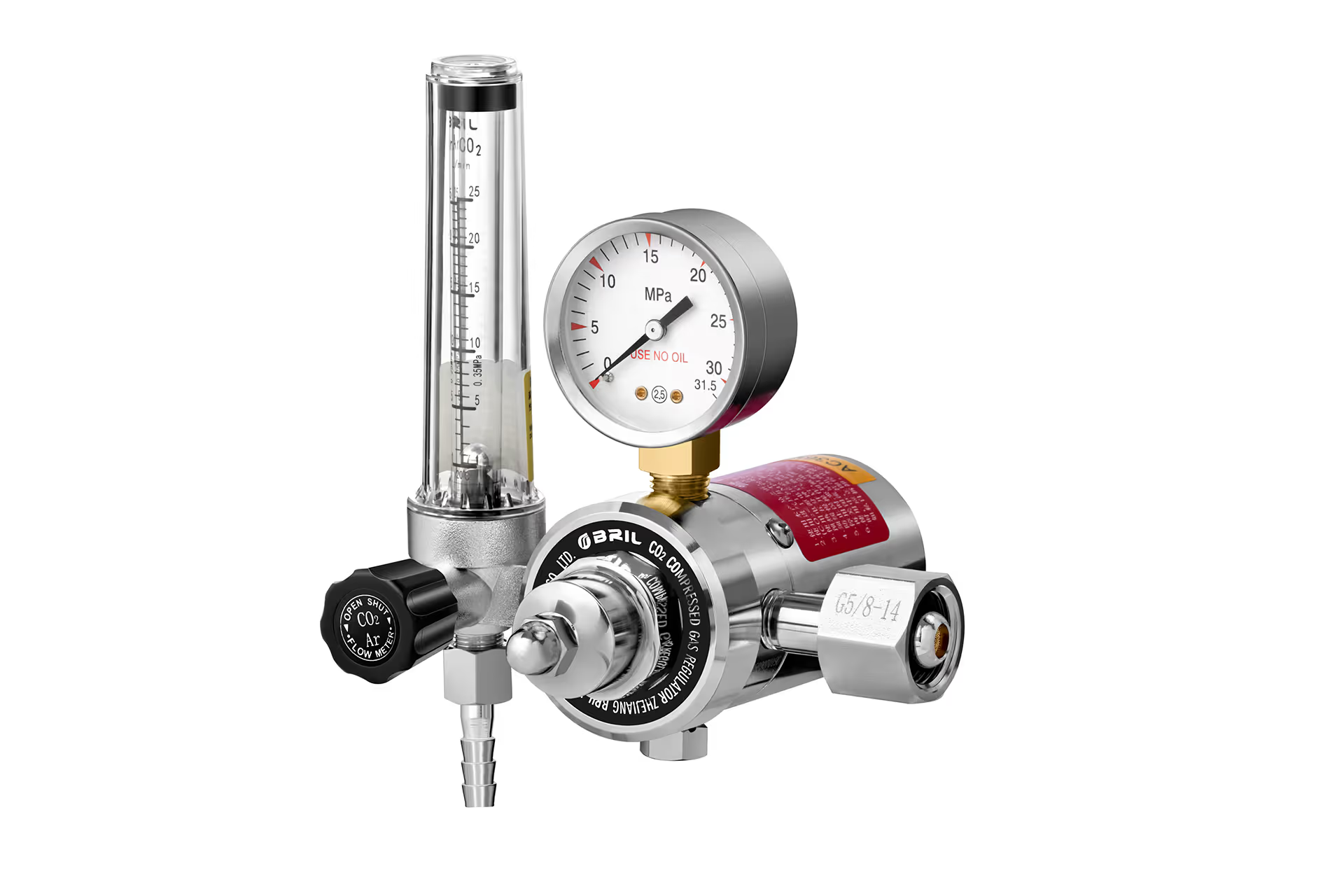
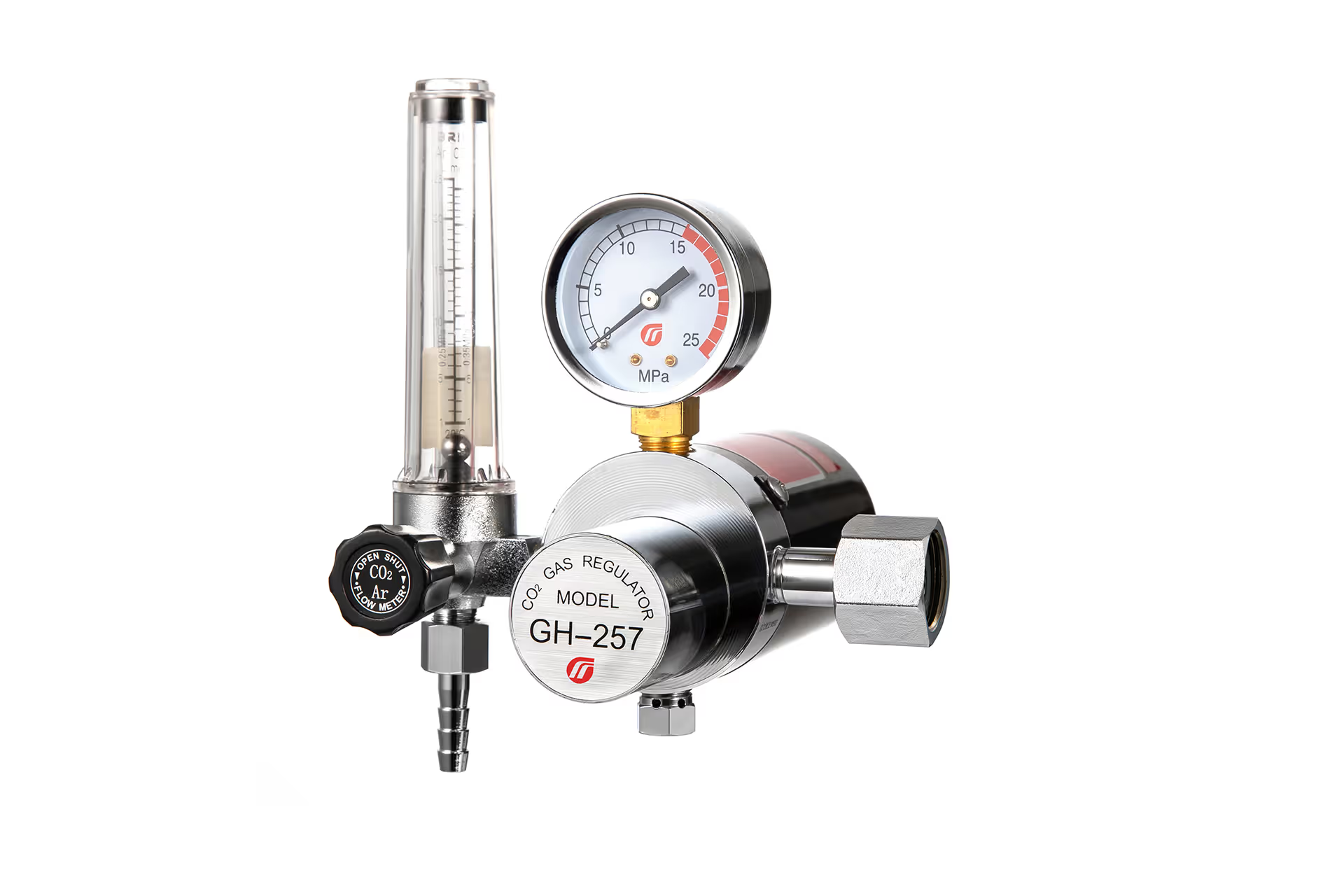
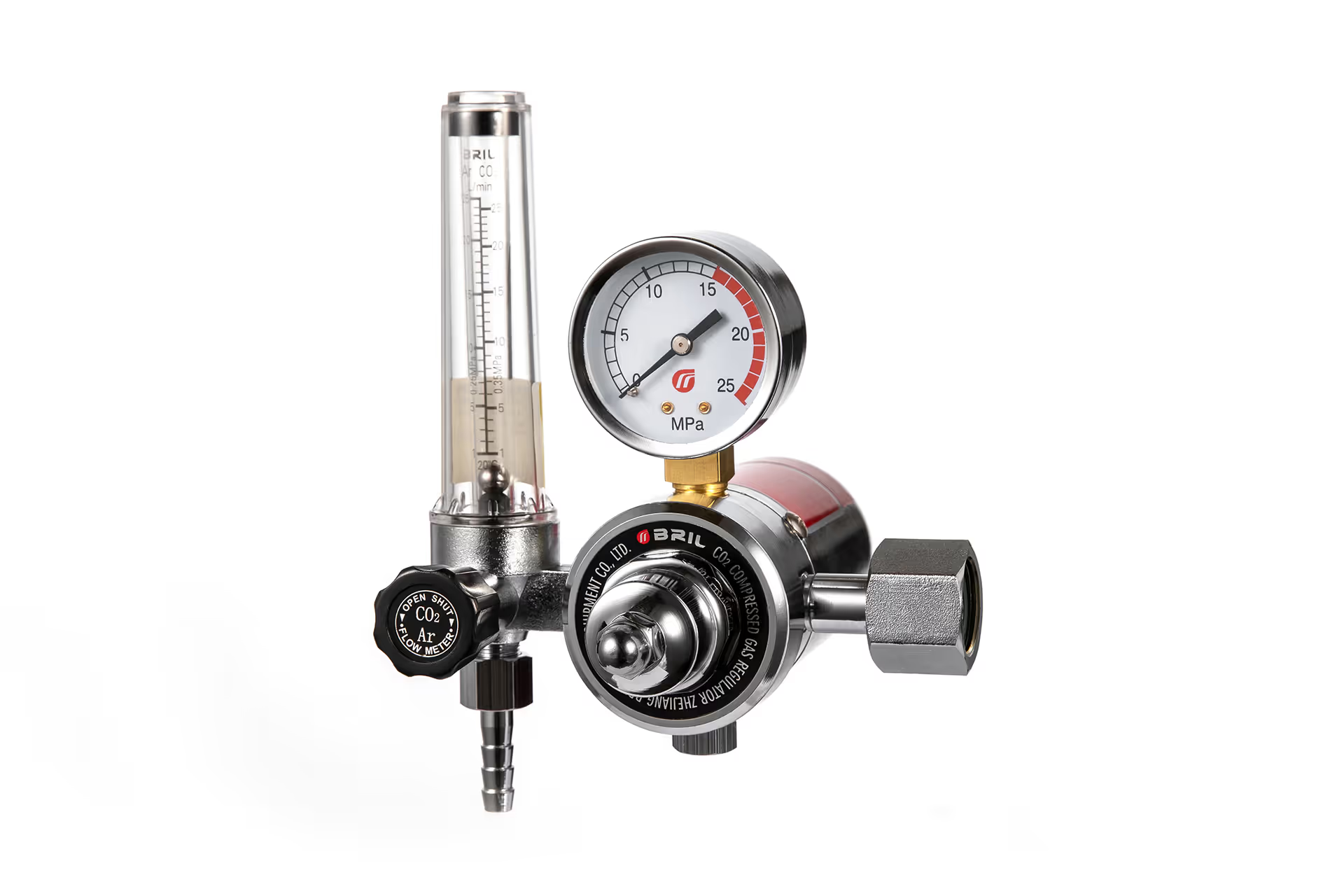
An argon regulator with flowmeter for TIG welding helps control shielding gas delivery from the cylinder to the torch. For welders, the objective is consistent protection around the weld pool. For distributors and equipment brands, the challenge is selecting a product that combines dependable pressure reduction, readable flow measurement, compatible connections, and repeatable manufacturing quality.
As a manufacturer and supplier of industrial gas regulators, we focus on precision manufacturing, brass materials, stable pressure control, and customized OEM and ODM solutions. However, selecting the right TIG welding regulator requires more than comparing appearance or maximum flow capacity.
How an Argon Regulator with Flowmeter Works
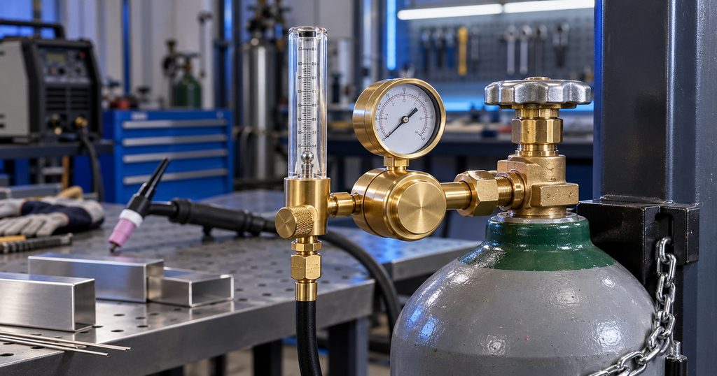
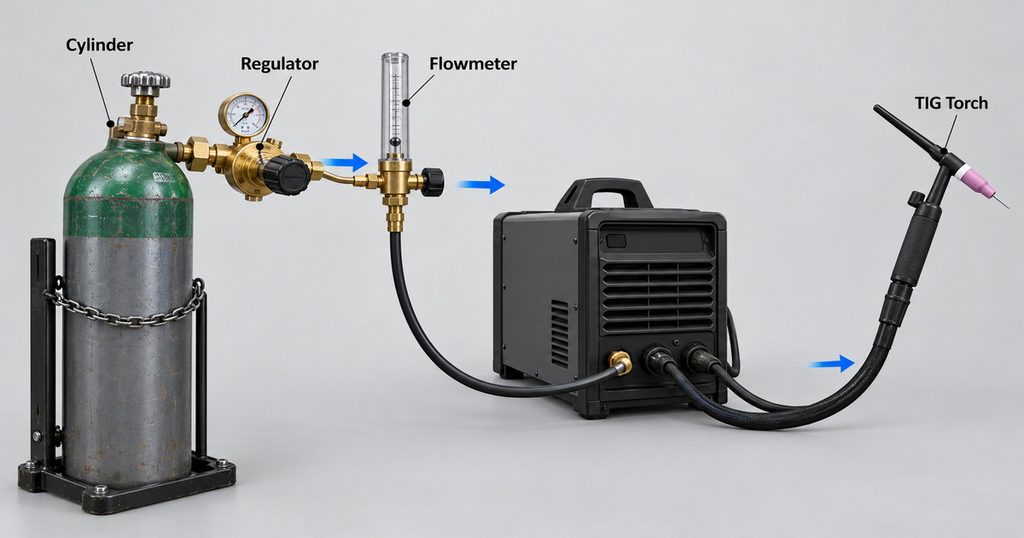
A regulator and a flowmeter perform different functions within the same gas delivery system.
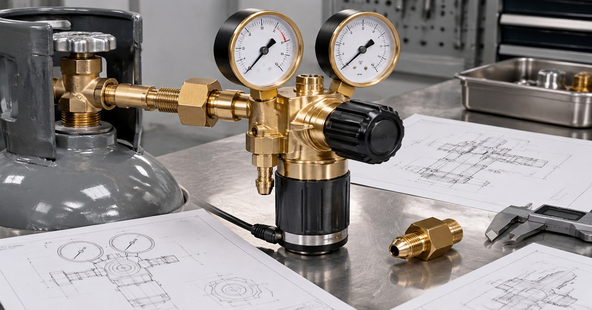
The regulator reduces high cylinder pressure to a controlled downstream pressure. The flowmeter indicates gas flow through the assembly, typically in cubic feet per hour, abbreviated CFH, or liters per minute, abbreviated L/min.
The cylinder pressure gauge serves another purpose: it displays inlet pressure. It does not directly measure shielding gas flow at the torch.
Pressure Regulation Is Not Flow Measurement
A pressure reading alone cannot confirm adequate shielding coverage. Actual delivery depends on the regulator, flow-control valve, hoses, welding machine, and torch.
Restrictions, leaks, or incorrect calibration conditions can affect the relationship between the displayed setting and delivered gas.
For this reason, buyers should evaluate the complete assembly rather than treating the regulator body and flow tube as unrelated components.
Flowmeter Regulators and Flow-Gauge Regulators
A flowmeter regulator commonly uses a transparent tube with a floating indicator. A flow-gauge regulator uses a dial calibrated to indicate flow under specified operating conditions.
Both require correct installation and operation.
For a tube-style flowmeter, follow the manufacturer’s mounting orientation and float-reading instructions. Do not assume every design uses the same reference point on the floating indicator.
Why Shielding Gas Control Matters in TIG Welding
TIG welding relies on shielding gas to protect the tungsten electrode and molten weld pool from atmospheric contamination.
Miller identifies 100% argon as the best all-around shielding gas for TIG welding. Argon/helium blends also serve specific applications, including some thicker-material welding requirements.
The regulator’s role is to support predictable gas delivery. It cannot compensate for dirty material, incorrect torch positioning, unsuitable consumables, or an uncontrolled draft.
More Gas Does Not Always Improve Protection
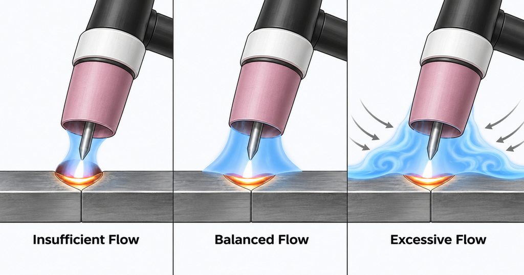
Excessive flow can create turbulence and draw surrounding air into the shielding envelope. This means increasing the setting may worsen contamination rather than solve it.
A better approach is to use the lowest effective flow for the actual torch configuration and working conditions.
This distinction matters commercially. A regulator should offer controllable adjustment within the useful operating range, not merely advertise a high maximum flow.
Recommended Argon Flow Rate for TIG Welding
Miller’s general TIG guidance recommends 15–20 CFH as a practical starting point. This is approximately 7–9.4 L/min.
Its shielding-gas guidance also describes a broader typical range of 10–35 CFH, depending on consumables and surrounding conditions.
These figures are starting references, not universal specifications.
| Application condition | Practical approach |
|---|---|
| Routine indoor TIG welding | Start around 15–20 CFH and verify coverage |
| Different cup size or tungsten extension | Reassess flow using the torch manufacturer’s guidance |
| Drafts near the welding area | Control airflow before substantially increasing gas |
| Larger shielding requirements | Validate the setting through the welding procedure |
| Suspected gas starvation | Check restrictions and leaks before changing the setting |
Set Flow While Gas Is Actually Moving
Adjust the flowmeter with gas flowing through the normal delivery path, using the machine’s gas-test or purge function where available.
A static reading does not establish the operating flow during welding.
Keep hoses connected as they will be used, and check that valves and torch components are not restricting delivery.
Treat Preflow and Postflow Separately
The flowmeter setting determines gas delivery rate. Preflow and postflow determine how long gas runs before and after the arc.
Follow the welding machine and torch instructions for these timing settings. Increasing flow is not a substitute for appropriate postflow protection.
How to Choose an Argon Flowmeter Regulator
A suitable regulator must match the cylinder supply, welding system, destination market, and expected duty.
Confirm Gas Service and Calibration
Specify argon service clearly.
If a product includes multiple gas scales, identify the correct scale and its calibration conditions. Do not assume a reading on one gas scale applies accurately to another gas.
Likewise, do not interchange regulators intended for oxygen, acetylene, propane, CO₂, or nitrogen simply because the connections appear adaptable.
Match Cylinder and Hose Connections
Confirm the cylinder valve connection used in the destination market, along with the outlet fitting and hose connection.
Record:
– Inlet connection designation.
– Outlet thread and sealing arrangement.
– Maximum rated inlet pressure.
– Required working-pressure conditions.
– Applicable cylinder supply configuration.
Avoid describing a connection as “universal” unless compatibility has been established for each intended configuration.
Choose a Readable, Useful Flow Range
A large scale is not automatically better.
The selected range should make normal TIG settings easy to read and adjust. Buyers should assess scale spacing, visibility, adjustment sensitivity, and labeling in the units used by their customers.
Evaluate Brass Construction Beyond Appearance
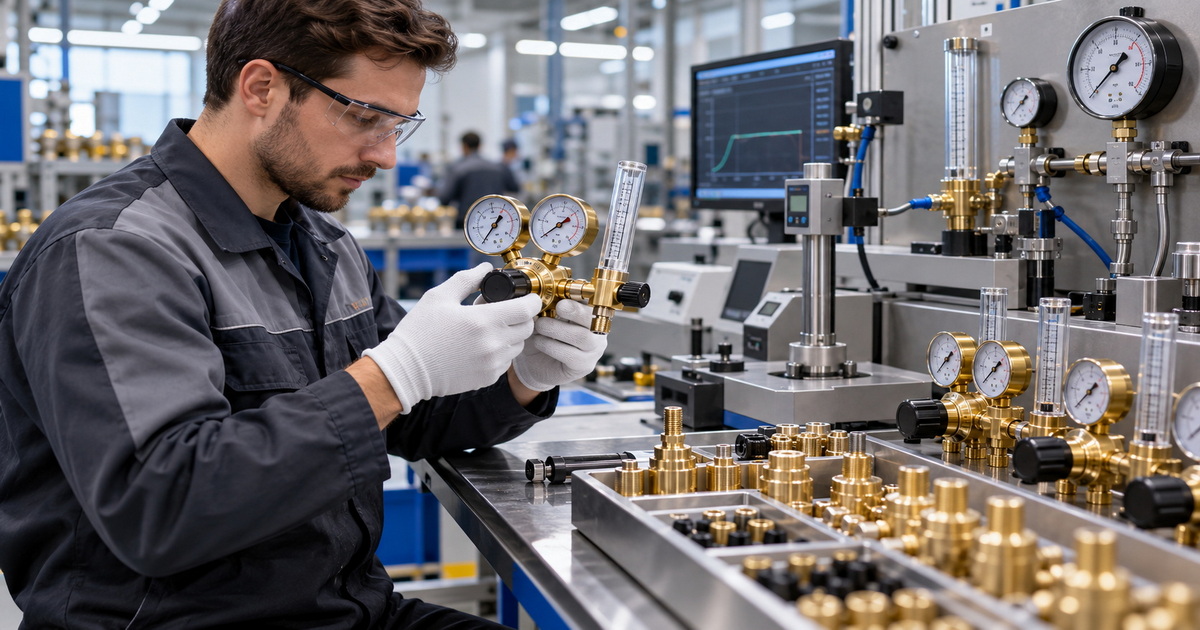
Our manufacturing approach emphasizes high-quality brass and precision machining.
For procurement, those descriptions should translate into verifiable requirements: specified material, thread dimensions, sealing-surface quality, assembly consistency, and documented inspection.
A polished exterior does not independently establish pressure stability, leak tightness, or service life.
Single-Stage vs. Dual-Stage Argon Regulators
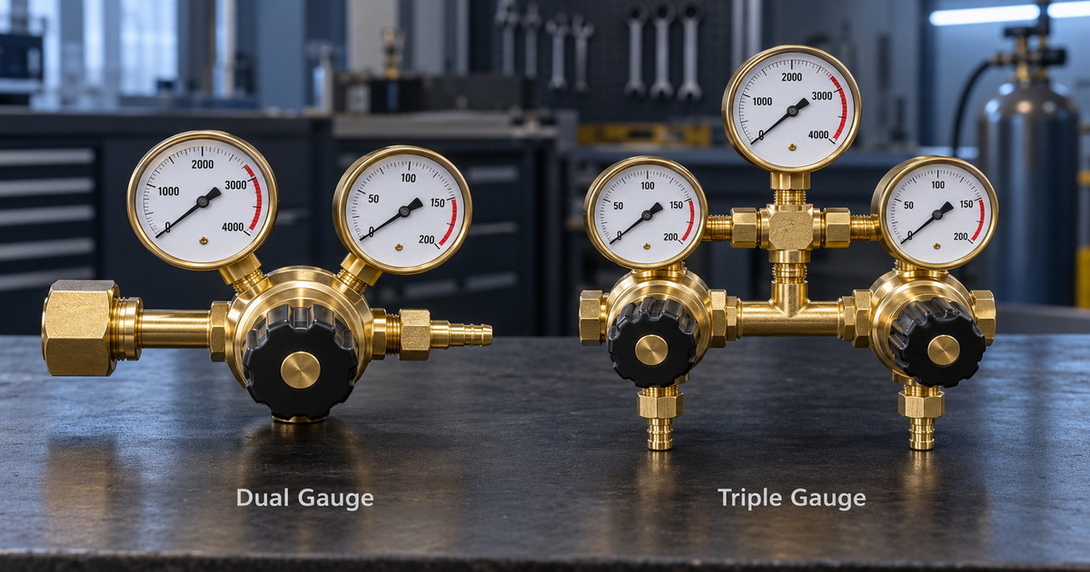
Single-stage regulators reduce pressure in one step. Dual-stage regulators use two successive pressure-reduction stages.
Harris explains that two-stage construction reduces the effect of changing cylinder pressure on final delivery pressure.
| Consideration | Single-stage design | Dual-stage design |
|---|---|---|
| Pressure reduction | One stage | Two stages |
| Supply-pressure variation | Greater influence may require adjustment | Reduced influence on outlet pressure |
| Selection priority | Suitable control at the required operating conditions | Greater delivery-pressure consistency |
| Verification needed | Performance across intended inlet pressures | Performance across intended inlet pressures |
When Dual-Stage Control Adds Value
Consider a dual-stage gas regulator when the process requires greater pressure consistency as cylinder pressure decreases.
However, two-stage pressure regulation does not independently guarantee constant flow at the torch. Downstream restrictions, flowmeter conditions, leaks, and torch configuration still matter.
Specify performance requirements first, then select the design that meets them.
Step-by-Step Setup for an Argon Regulator with Flowmeter
Always follow the regulator, cylinder supplier, and welding equipment instructions. The sequence below is a general checklist, not a replacement for model-specific procedures.
1. Secure the cylinder in its intended operating position.
2. Confirm that the regulator matches the gas, cylinder connection, and inlet-pressure rating.
3. Inspect fittings, sealing surfaces, gauges, and the flow tube for damage.
4. Connect the assembly using the specified sealing method.
5. Position the flowmeter as instructed by its manufacturer.
6. Open the cylinder valve slowly according to the supplier’s procedure.
7. Check connections using an approved leak-detection method.
8. Activate gas flow through the welding system.
9. Adjust the flow and assess shielding during a controlled test weld.
10. Follow the specified shutdown and depressurization procedure.
Do not use a flame to check for leaks. Stop using equipment that shows damage, leakage, or abnormal pressure behavior.
Troubleshooting Poor Shielding and Unstable Flow
Poor weld appearance does not automatically mean the regulator is defective.
Use a structured diagnosis before replacing equipment or increasing gas consumption.
| Symptom | Possible causes to investigate | First check |
|---|---|---|
| Porosity or contamination | Leaks, drafts, excessive flow, dirty material | Inspect the gas path and working environment |
| Low indicated flow | Closed valve, restriction, depleted supply | Check supply and downstream components |
| Unstable float | Changing conditions, incorrect orientation, restriction | Verify installation and operating conditions |
| Normal indication but poor coverage | Downstream leak, torch issue, unsuitable setup | Inspect delivery to the torch |
| Unexpected pressure behavior | Regulator malfunction or incorrect configuration | Stop operation and arrange qualified inspection |
Check the System Before Blaming One Component
If the flowmeter indicates normal flow but shielding remains poor, inspect hoses, connectors, torch seals, and consumables.
Where appropriate, a suitable torch-end flow-checking device can help compare delivered flow with the regulator indication.
The goal is to locate the problem, not mask it with a higher setting.
A Practical Acceptance Plan for Distributors and OEM Buyers
A purchasing specification should define what acceptable performance means.
Before production approval, agree on test conditions and acceptance criteria with the supplier. This is more useful than relying on broad statements such as “industrial quality.”
Verify Performance Across Operating Conditions
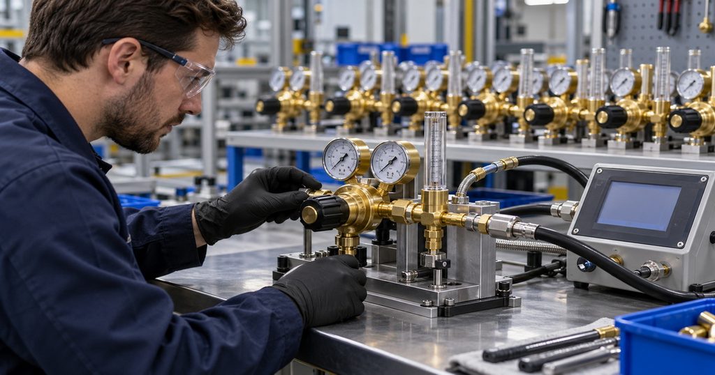
A practical evaluation plan can include:
– Leak testing under defined conditions.
– Flow indication checks at selected operating points.
– Outlet-pressure behavior at different inlet pressures.
– Pressure stability after downstream flow stops.
– Adjustment repeatability.
– Thread and connection inspection.
– Gauge, scale, and label verification.
Acceptance limits should reflect the product design and intended application. No single tolerance should be presented as suitable for every regulator.
Preserve Traceability
Ask how production batches, inspection records, and approved specifications are linked.
For repeat orders, the important question is whether the delivered product remains consistent with the approved sample—not simply whether it looks similar.
OEM and ODM Argon Regulator Manufacturing
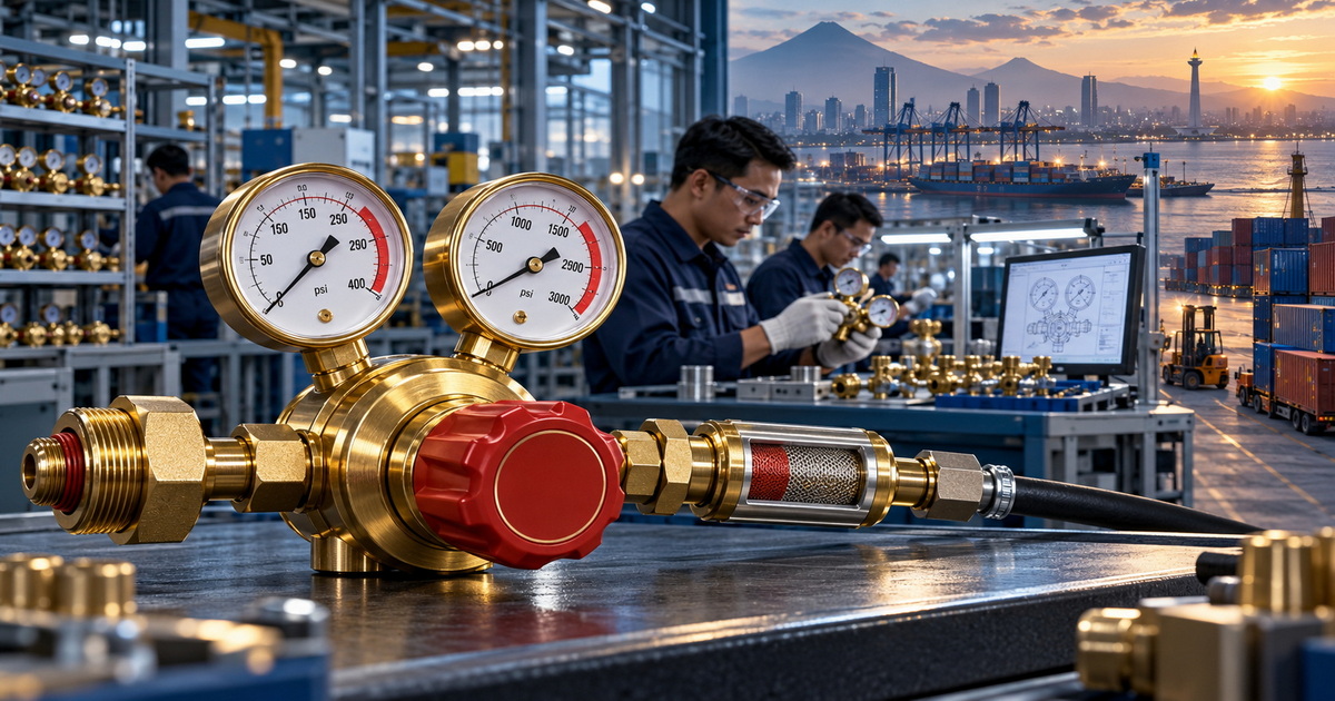
We supply CO₂ regulators, heated CO₂ regulators, argon regulators, oxygen regulators, acetylene regulators, propane regulators, nitrogen regulators, and dual-stage gas regulators for welding, cutting, and industrial applications.
For overseas brands, wholesalers, distributors, and manufacturers, customization should begin with the destination market and operating requirements.
Define the Specification Before Customizing Appearance
An OEM or ODM brief should identify:
– Gas service and pressure ratings.
– Flow range, units, and calibration conditions.
– Cylinder and outlet connections.
– Regulator stage configuration.
– Material and inspection requirements.
– Branding, packaging, and instruction languages.
– Required documentation for the destination market.
Our focus on customized gas-control solutions supports this specification-led approach.
Any claim of compliance with international standards should identify the relevant standard and supporting documentation for the specific model. A general company statement is not a substitute for product-level evidence.
Request a Specification-Based Quotation
Looking for an argon regulator with flowmeter for TIG welding under your own brand?
Send us your target market, cylinder connection, required flow range, order quantity, and customization requirements. We can discuss a suitable OEM or ODM configuration and define the inspection and documentation scope before sample approval.
Frequently Asked Questions
1.What Is the Best Argon Flow Rate for TIG Welding?
Around 15–20 CFH is a practical starting point for many routine applications. Adjust according to consumables, working conditions, and the approved welding procedure.
2.Can I Use an Argon/CO₂ Welding Mix for TIG?
Do not assume a MIG shielding-gas blend is suitable for TIG. Miller recommends pure argon as the general-purpose choice, with argon/helium blends used for particular applications.
3.Why Does Increasing Gas Flow Make My Weld Worse?
Excessive flow can cause turbulence and introduce atmospheric contamination. Check drafts, leaks, torch setup, and material cleanliness instead of continually increasing the setting.
4.Does a Dual-Stage Regulator Guarantee Constant Flow?
No. It improves delivery-pressure consistency as supply pressure changes, but flow still depends on the flow-control assembly and downstream system.
5.Can One Regulator Be Used for Different Industrial Gases?
Only where the manufacturer explicitly specifies compatibility. Gas service, pressure rating, materials, connections, and calibration must all be appropriate.
6.What Information Should I Send for an OEM Quotation?
Provide the target market, gas type, inlet pressure, flow range, connections, stage configuration, quantity, branding requirements, and required documentation.
References
1. Miller Electric, “Best Practices for Proper Shielding Gas in TIG Welding.” Source for shielding-gas selection, typical flow ranges, and excessive-flow considerations. [View source]. [millerwelds]
2. Miller Electric, “Guide to TIG Welding Basics.” Source for the 15–20 CFH starting range and checking restrictions in the gas delivery system. [View source]. [millerwelds]
3. Miller Electric, “Common TIG Welding Problems.” Source for troubleshooting shielding problems and the relationship between excessive flow, turbulence, and contamination. [View source]. [millerwelds]
4. Harris Products Group, “Specialty Gas Pressure & Flow Control Equipment Catalog.” Source for single-stage and two-stage pressure reduction and delivery-pressure stability. [View source]. [ch-delivery.lincolnelectric]
5. Miller Electric, “Argon/CO₂/Helium Flowmeter Regulator, 30 PSIG.” Product documentation illustrating specified flow ranges, gas scales, and preset pressure conditions; not a specification for our products. [View source]. [millerwelds]
Hot Tags: Argon Regulator, Argon Flowmeter Regulator, TIG Welding Gas Regulator, Argon Regulator with Flowmeter, Welding Gas Regulator, Dual Stage Argon Regulator, Argon Regulator Manufacturer, Argon Regulator Supplier, OEM Gas Regulator, Industrial Gas Regulator