Content Menu
● Pressure Regulator vs Flowmeter: Key Differences
● How a MIG Welding Pressure Regulator Works
>> Why a Pressure Gauge Cannot Confirm Torch Flow
>> What a Dial-Type Flowgauge Actually Measures
● How a MIG Welding Flowmeter Works
>> Gas and Calibration Pressure Matter
>> A Flowmeter Is Not a Substitute for Pressure Reduction
● Which Is Better for MIG Welding?
>> Choose a Flowgauge Regulator When Portability Matters
>> Choose a Flowmeter Regulator When Visual Adjustment Matters
>> Choose Two-Stage Regulation for Supply-Pressure Stability
● What Shielding-Gas Flow Rate Should You Use?
>> More Flow Does Not Always Mean Better Shielding
● Three Overlooked Factors That Affect Real Workshop Performance
>> 1. Cylinder-End Readings Do Not Prove Nozzle Delivery
>> 2. Start-Up Surges Can Hide Behind Normal Steady Flow
>> 3. CO₂ Cooling Requires a Different Equipment Decision
● How to Set Up a MIG Welding Regulator Correctly
● What OEM Buyers Should Specify Before Ordering
● Specify a Gas-Control Assembly Around Your Application
>> 1.Can I use a pressure regulator without a flowmeter for MIG welding?
>> 2.Is a floating-ball flowmeter always more accurate than a dial regulator?
>> 3.Can the same flowmeter measure argon and CO₂?
>> 4.Does a two-gauge regulator provide two-stage regulation?
>> 5.Why does porosity continue when the flowmeter reading looks correct?
>> 6.Do all CO₂ welding applications need a heated regulator?
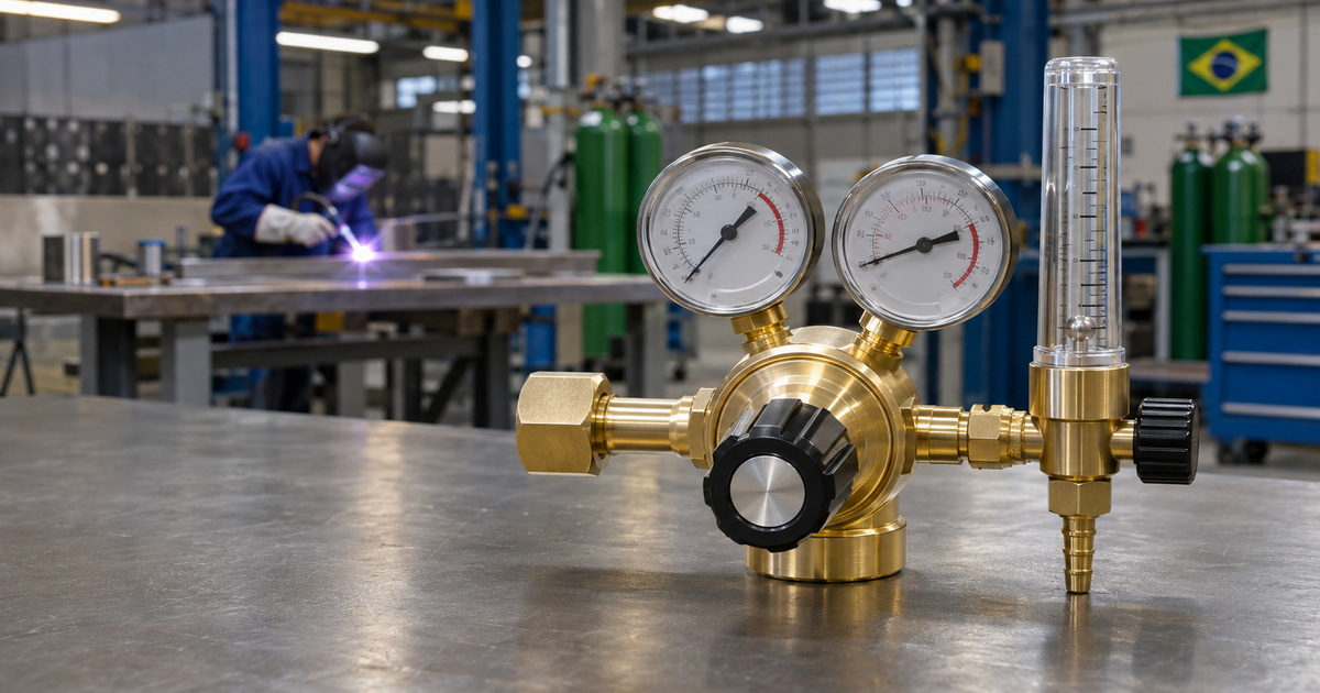
Choosing between a pressure regulator vs flowmeter for MIG welding starts with one important distinction: they perform different jobs. A pressure regulator reduces cylinder pressure to a usable level. A flowmeter indicates shielding-gas flow. Most cylinder-fed MIG welding systems need both functions, often combined in one assembly.
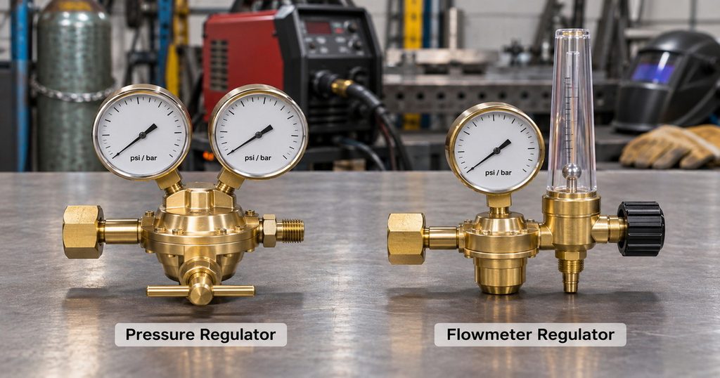
Pressure Regulator vs Flowmeter: Key Differences
| Comparison point | Pressure-only regulator | Dial-type flowgauge regulator | Tube-type flowmeter regulator |
|---|---|---|---|
| Main function | Reduces and controls pressure | Reduces pressure and indicates calibrated flow | Reduces pressure and indicates flow through a tube |
| Typical display | Cylinder and delivery pressure | Cylinder pressure and a flow-calibrated dial | Cylinder pressure and a floating ball or float |
| Common units | PSI or bar | SCFH or L/min | SCFH or L/min |
| Flow indication | Requires a separate device | Inferred from pressure through a specified restriction | Indicated by float position under calibrated conditions |
| Main advantage | Suitable pressure supply for compatible downstream equipment | Compact, rugged construction | Clear visual feedback during adjustment |
| Main limitation | Pressure does not establish actual torch flow | Accuracy depends on its intended configuration | Reading depends on gas, calibration, and installation |
| Typical application | Systems with separate downstream flow control | Portable equipment and routine fabrication | Workshops prioritizing visible flow adjustment |
Neither complete regulator type is automatically superior. The right choice depends on operating conditions, calibration, durability requirements, and how the complete gas circuit behaves.
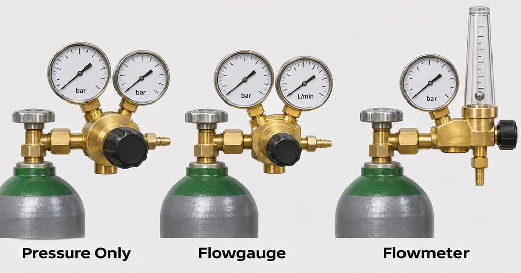
How a MIG Welding Pressure Regulator Works
A shielding-gas cylinder stores gas at pressures unsuitable for direct delivery to a welding gun. The regulator reduces that pressure and supplies the downstream equipment within its rated operating range.
However, pressure and flow describe different things.
Pressure describes the gas condition at a particular point. Flow describes how much gas passes through the system over time. The same delivery pressure can produce different flow rates when hose restrictions, valves, or nozzle conditions change.
Why a Pressure Gauge Cannot Confirm Torch Flow
A pressure gauge may show an apparently normal reading while a blocked hose or closed solenoid prevents gas from reaching the weld.
Conversely, a downstream leak can consume gas without providing adequate shielding.
The practical lesson is straightforward: do not choose a MIG gas regulator solely because its pressure range looks suitable. Confirm how flow will be controlled and checked.
What a Dial-Type Flowgauge Actually Measures
A flowgauge regulator commonly uses variable pressure across a specified fixed restriction. Its dial converts that pressure relationship into a flow indication.
Although the display reads SCFH or L/min, its underlying mechanism differs from a floating-ball flowmeter.
That does not make it unsuitable. A correctly specified flowgauge regulator can provide dependable shielding-gas control. Problems arise when users change restrictions, use an unsuitable gas scale, or interpret the dial outside the conditions for which it was designed.
How a MIG Welding Flowmeter Works
A common welding flowmeter contains a tapered tube and a floating ball or other float. Flowing gas lifts the float until the forces acting on it balance.
The operator reads the indicated flow against the appropriate scale.
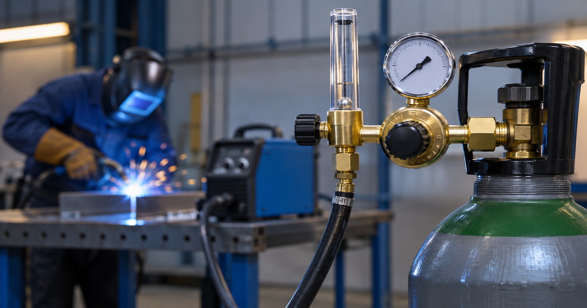
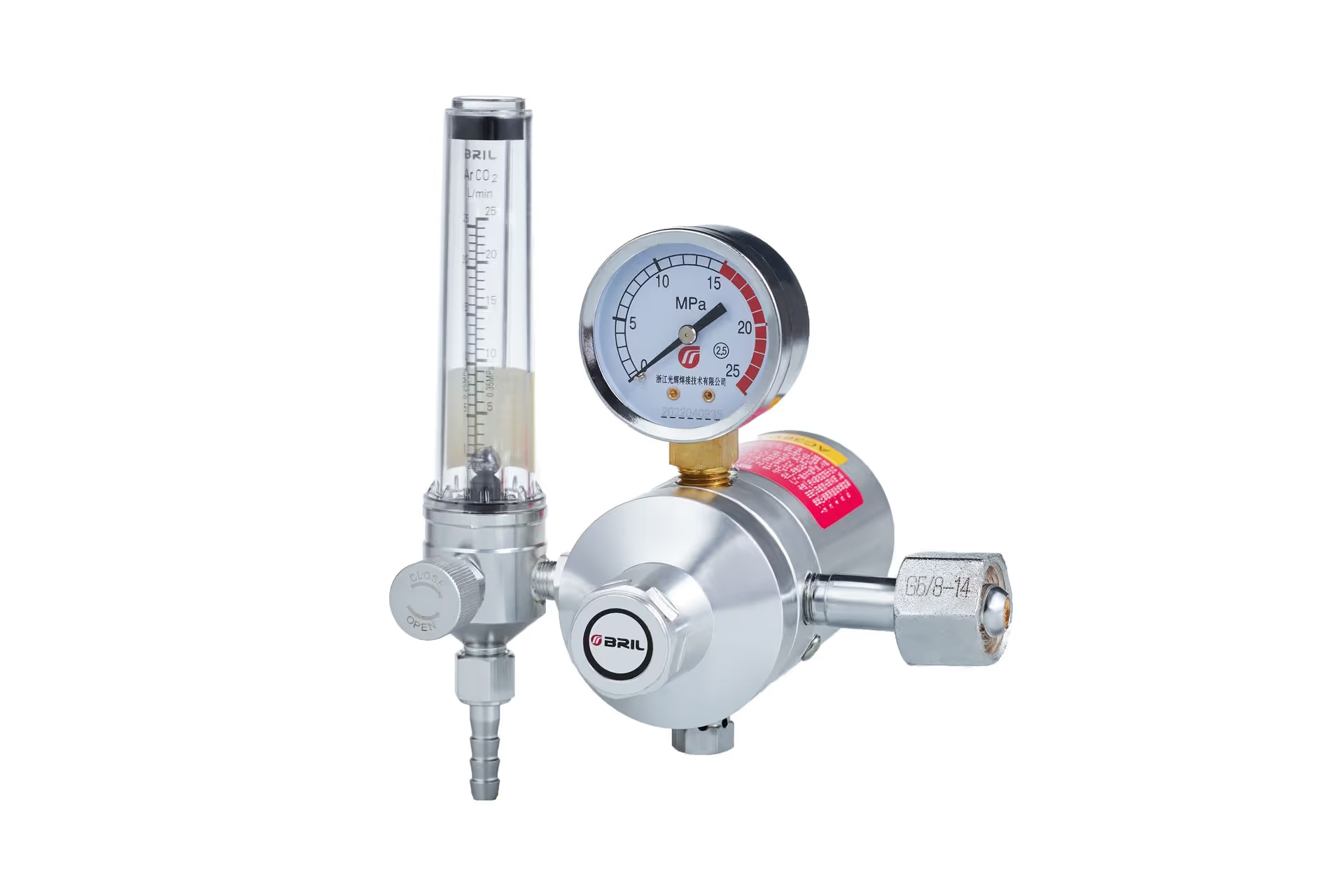
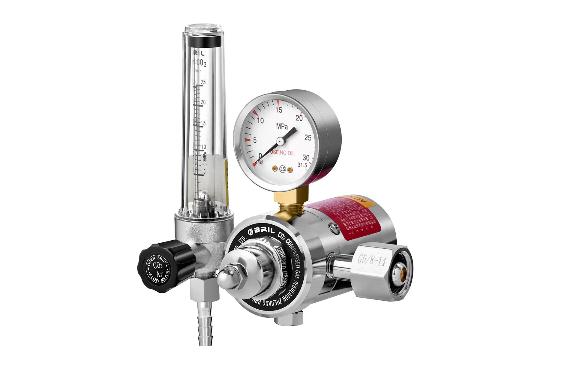
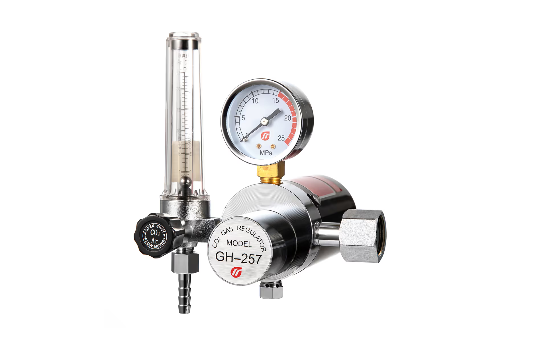
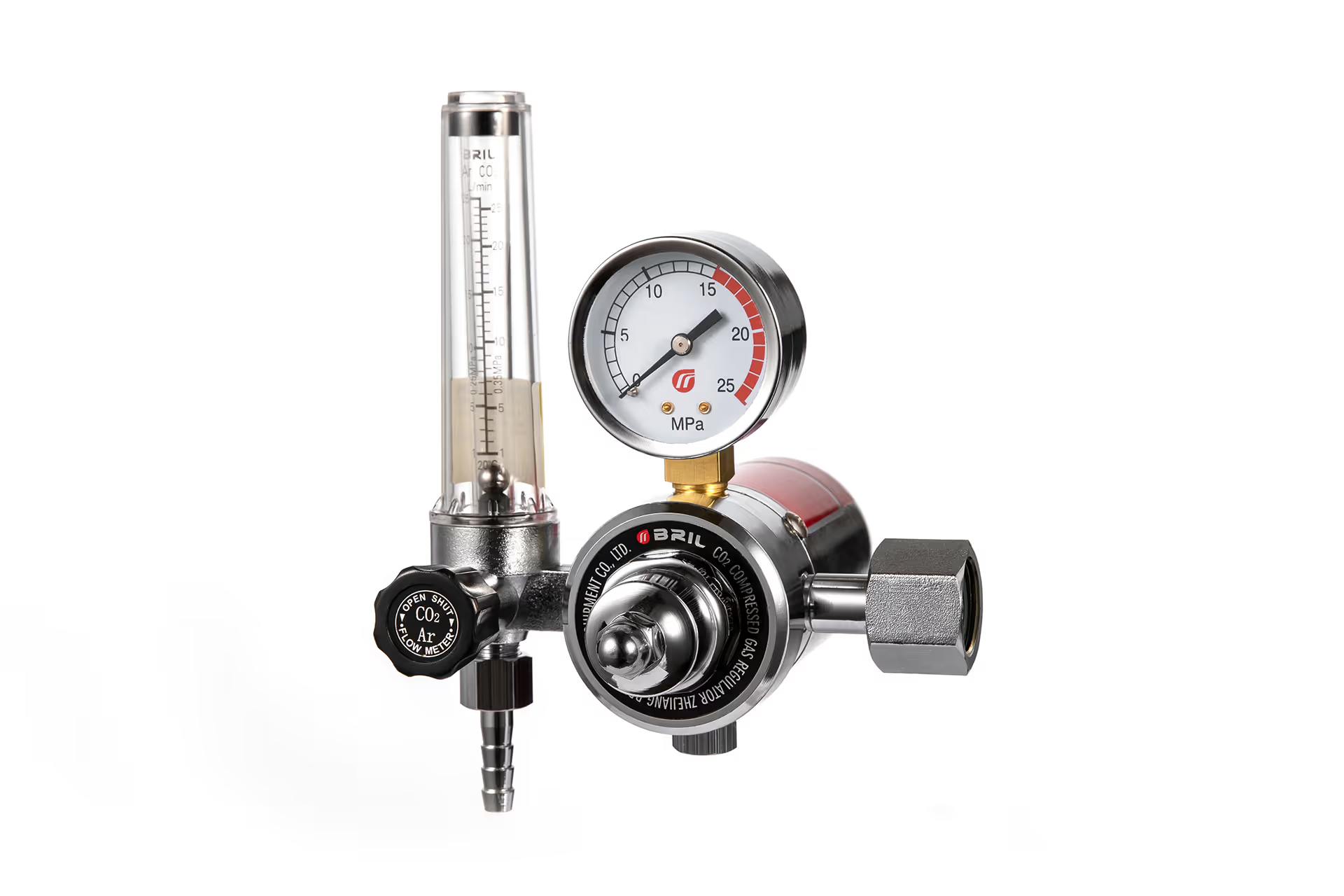
A complete flowmeter regulator normally combines pressure reduction, a flow tube, and an adjustment valve. A standalone flowmeter may instead require an existing regulated supply.
Gas and Calibration Pressure Matter
A flow tube is not universally accurate for every gas or inlet pressure.
Before installation, verify:
– The approved gas or shielding-gas mixture.
– The required operating or calibration pressure.
– The usable measurement range.
– The prescribed mounting orientation.
– The correct float-reading position.
Do not assume every ball is read at its center or every float at its top. Follow the instructions supplied with that model.
Many conventional tubes require upright installation. Some specialized designs accommodate tilt, but that capability should be documented rather than assumed.
A Flowmeter Is Not a Substitute for Pressure Reduction
Never connect a standalone flowmeter to cylinder pressure unless it is explicitly designed and rated for that arrangement.
A product described as a “flowmeter” may be a low-pressure pipeline instrument, not a complete cylinder regulator. This distinction is particularly important when sourcing components for private-label assemblies.
Which Is Better for MIG Welding?
For a fixed welding station, a well-specified tube-type flowmeter regulator is often attractive because operators can see and adjust the flow indication easily.
For portable fabrication, a compact flowgauge regulator may be preferable because it avoids an exposed vertical measuring tube.
Neither option compensates for leaks, blocked passages, incorrect shielding gas, or poor welding technique.
Choose a Flowgauge Regulator When Portability Matters
Consider a dial-type unit when:
– Equipment moves frequently between work areas.
– Impact exposure is a significant concern.
– Space around the cylinder is limited.
– Operators use a consistent, validated setup.
Evaluate dial readability and useful adjustment resolution, not simply maximum flow capacity.
Choose a Flowmeter Regulator When Visual Adjustment Matters
Consider a tube-type assembly when:
– Operators regularly change flow settings.
– Supervisors need convenient visual checks.
– Several approved gas scales are useful.
– The installation allows correct tube positioning.
A visible float makes adjustment intuitive, but it does not prove that every indicated litre reaches the torch.
Choose Two-Stage Regulation for Supply-Pressure Stability
A two-stage regulator reduces pressure in two successive steps. Its purpose is to limit delivery-pressure changes as cylinder pressure falls.
That can benefit applications requiring consistent delivery conditions.
Two-stage regulation and flowmeter selection are separate decisions. A regulator with two gauges is not necessarily two-stage, and a two-stage regulator does not eliminate the need to verify shielding-gas flow.
What Shielding-Gas Flow Rate Should You Use?
There is no universal MIG welding gas-flow setting.
Published manufacturer guidance includes approximately 20 CFH for some light-duty work and 25–35 CFH for short-circuit MIG welding. These correspond to roughly 9.4 L/min and 11.8–16.5 L/min, respectively.
Treat these as starting references, not a welding procedure.
The correct setting depends on:
– Nozzle diameter and condition.
– Welding position and joint geometry.
– Transfer mode and operating parameters.
– Torch angle and distance from the work.
– Drafts and extraction arrangements.
– The approved welding procedure.
More Flow Does Not Always Mean Better Shielding
Too little gas can leave the weld pool inadequately protected.
Excessive flow wastes gas and can create turbulence that draws surrounding air into the shielding envelope. Increasing flow indefinitely is therefore not a reliable response to porosity.
Inspect coverage conditions, cleanliness, leaks, and gun assembly before assuming that the regulator setting is too low.
Three Overlooked Factors That Affect Real Workshop Performance
1. Cylinder-End Readings Do Not Prove Nozzle Delivery
A cylinder-mounted instrument indicates conditions at its own location.
Between that instrument and the weld are hoses, fittings, the machine solenoid, gun connections, and gas passages. Leaks or restrictions anywhere along that route can change delivery.
When diagnosing inconsistent shielding:
1. Confirm the regulator or flowmeter setting.
2. Check connections with an approved leak-detection solution.
3. Inspect hoses, gun seating, diffuser, and nozzle.
4. Measure delivery at the nozzle using a suitable torch-end flow checker.
5. Compare results under the same operating conditions.
A discrepancy is diagnostic evidence, not automatic proof that the regulator is defective.
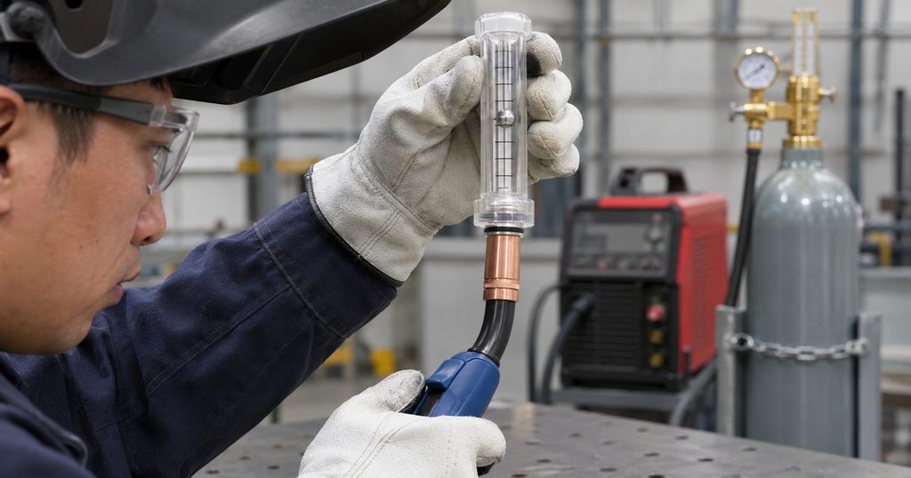
2. Start-Up Surges Can Hide Behind Normal Steady Flow
When the welding solenoid closes, gas can remain pressurized in the supply hose. Reopening the valve may release a brief surge before steady flow develops.
A normal steady-state reading does not describe that initial event.
For production involving many short welds, evaluate start-up behavior as well as continuous flow. Compatible surge-control equipment may help, but it must be selected for the system rather than added indiscriminately.
3. CO₂ Cooling Requires a Different Equipment Decision
CO₂ service can involve substantial cooling during pressure reduction and sustained withdrawal. Under demanding conditions, icing or unstable delivery may become an operational problem.
A flowmeter displays flow; it does not solve the underlying thermal limitation.
Depending on duty cycle and supply conditions, a CO₂ regulator with a suitable heat exchanger or an appropriately specified heated design may be worth evaluating. These are different solutions and should not be treated as interchangeable.
For heated models, specify supply voltage, electrical protection, environmental suitability, and continuous operating capability. Never improvise external heating around a cylinder or regulator.
How to Set Up a MIG Welding Regulator Correctly
Follow the instructions for the cylinder, regulator, and welding machine. A practical setup sequence includes:
1. Secure the cylinder in its required operating position.
2. Confirm the gas, valve connection, pressure rating, and regulator compatibility.
3. Inspect sealing surfaces and use only specified seals and fittings.
4. Install the assembly according to its instructions.
5. Position the flow tube correctly, where applicable.
6. Open the cylinder valve slowly using the prescribed procedure.
7. Check connections for leaks.
8. Activate gas flow using the machine’s purge function or approved method.
9. Adjust flow while gas is moving, not merely while the system is pressurized.
10. Verify nozzle delivery and make a representative test weld.
Use a safe purge arrangement that avoids unintended wire feeding or arc initiation. At shutdown, follow the equipment manufacturer’s isolation and depressurization procedure.
What OEM Buyers Should Specify Before Ordering
| Specification | What to confirm |
|---|---|
| Gas service | Exact gas and permitted mixtures |
| Inlet connection | Destination-market cylinder standard |
| Pressure ratings | Maximum inlet and required delivery conditions |
| Flow indication | Flowgauge or tube-type design |
| Calibration | Gas, pressure, range, and reading instructions |
| Construction | Brass specification, seals, diaphragm, protective features |
| Verification | Leak testing and functional inspection criteria |
| Documentation | Instructions, traceability, and applicable conformity evidence |
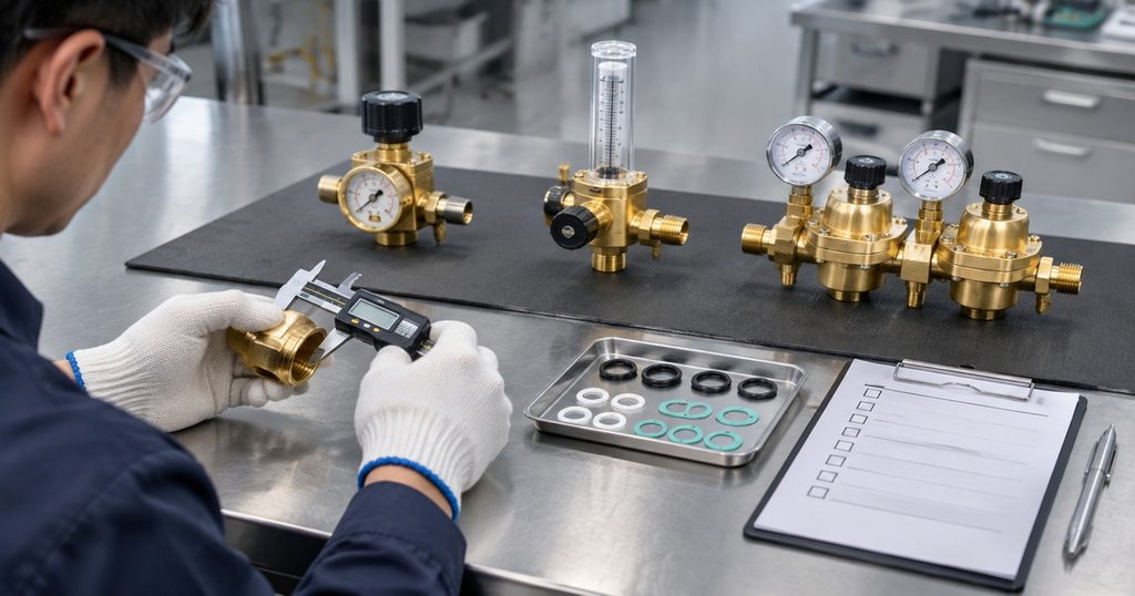
Specify a Gas-Control Assembly Around Your Application
We manufacture and supply CO₂ regulators, heated CO₂ regulators, argon regulators, and other industrial gas-control products, with OEM and ODM support for overseas brands, wholesalers, distributors, and equipment manufacturers.
For your next MIG regulator project, send us your shielding gas, cylinder connection standard, required flow range, operating environment, and branding requirements.
We can discuss a customized brass gas-control assembly, inspection requirements, and documentation needs around those specifications—rather than asking you to select by appearance alone.
Frequently Asked Questions
1.Can I use a pressure regulator without a flowmeter for MIG welding?
Yes, if the system includes another suitable means of controlling and verifying flow. A pressure-only gauge cannot independently confirm how much shielding gas reaches the torch.
2.Is a floating-ball flowmeter always more accurate than a dial regulator?
No. Accuracy depends on design, calibration, operating conditions, and installation. Compare documented performance over the intended working range rather than assuming one display style guarantees better results.
3.Can the same flowmeter measure argon and CO₂?
Some models provide approved scales for both. Others require a manufacturer-specified correction or a different instrument. Use the correct scale and operating conditions; do not assume the readings are interchangeable.
4.Does a two-gauge regulator provide two-stage regulation?
Not necessarily. Gauge count describes the displays. Stage count describes successive pressure-reduction mechanisms inside the regulator. Confirm the actual construction in the technical specification.
5.Why does porosity continue when the flowmeter reading looks correct?
Possible causes include downstream leaks, drafts, nozzle blockage, incorrect gun assembly, contaminated material, or excessive flow. Check nozzle delivery and the welding process before replacing the regulator.
6.Do all CO₂ welding applications need a heated regulator?
No. Heating requirements depend on withdrawal rate, duty cycle, ambient conditions, and supply configuration. Assess actual operating behavior and manufacturer guidance before specifying heated equipment.
References
1. Harris Products Group, *Controlling Gas Flow*. Technical explanation of pressure-based flowgauges and their calibrated restrictions. [harrisproductsgroup]
2. Harris Products Group, *Shielding Gas*. Discussion of fixed-pressure, variable-orifice devices and alternative flow-control configurations. [harrisproductsgroup]
3. Harris Products Group, *Two-Stage Regulators*. Explanation of staged pressure reduction and delivery-pressure stability as inlet pressure changes. [harrisproductsgroup]
4. Miller Electric, *What Type of Gas Is Best for MIG Welding in DIY Applications?* Guidance on short-circuit MIG flow settings, excessive flow, and torch-end verification. [millerwelds]
5. Miller Electric, *MIG Welding Tips and Techniques for Beginners*. Light-duty shielding-gas starting guidance. [millerwelds]
6. Miller Electric, *Tips for Troubleshooting Common MIG Weld Defects*. Guidance on leaks, drafts, nozzle condition, and shielding-related porosity. [millerwelds]
7. Miller/Smith, *Argon/CO₂/Helium Heavy-Duty Flowmeter Regulator, 30 PSIG*. Product-specific examples of gas scales, regulated pressure, and specialized float guidance. [millerwelds]
8. Miller/Smith, *CO₂ Flowmeter Regulator w/Heat Exchanger, 30 PSIG*. Example of equipment designed to reduce high-flow CO₂ freeze-up. [millerwelds]
9. Miller/Smith, *15001 Series Surge Protector, 20 CFH*. Example of equipment designed to address sudden shielding-gas surges. [millerwelds]
Hot Tags: MIG Welding Gas Regulator, Welding Gas Flowmeter, Shielding Gas Regulator, Argon Flowmeter Regulator, CO₂ Welding Regulator, MIG Welding Flowmeter Regulator, Industrial Gas Regulator Manufacturer, Welding Gas Regulator Supplier, OEM Welding Gas Regulator, Dual Stage Gas Regulator