Content Menu
● What Is the Difference Between an Argon Flowmeter and a Ball-Type Flowmeter?
>> Key takeaway
● Argon Flowmeter vs Ball-Type Flowmeter: Technical Comparison for Vertical Welding
● Why Vertical Welding Makes Shielding Gas Control More Demanding
>> Common symptoms of incorrect argon flow
● How a Ball-Type Argon Flowmeter Works
● Which Flowmeter Is Best for Vertical MIG Welding?
>> Choose an argon ball-type flowmeter regulator when:
>> Consider additional flow verification when:
● Recommended Argon Flow Settings for Vertical Welding
● Expert Setup Procedure for Vertical Welding Argon Flowmeters
>> 1. Confirm the gas and connection standard
>> 2. Secure the cylinder and inspect the equipment
>> 3. Install the ball-type flowmeter vertically
>> 4. Open the cylinder valve carefully
>> 6. Set the flow under live gas delivery
>> 7. Run a test weld and inspect the bead
>> 8. Record the approved setting
● Manufacturing Factors That Affect Flowmeter Reliability
>> Critical quality-control points
● Final Recommendation: Choose a Complete Argon Flowmeter Regulator
● FAQ
>> 1. Is an argon flowmeter the same as a ball-type flowmeter?
>> 2. Why must a ball-type flowmeter be installed vertically?
>> 3. Where should I read the ball on an argon flowmeter?
>> 4. What argon flow rate should I use for vertical TIG welding?
>> 5. Can excessive argon flow cause porosity?
>> 6. Can I use an argon-calibrated flowmeter for CO₂ or helium?
>> 7. How can I verify actual gas flow at the welding torch?
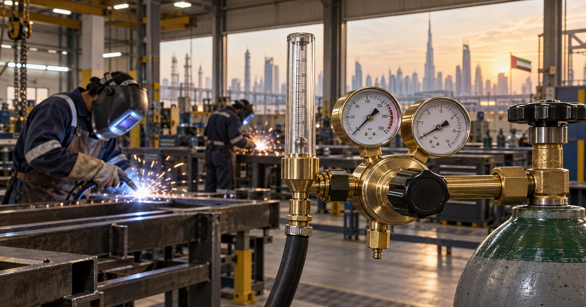
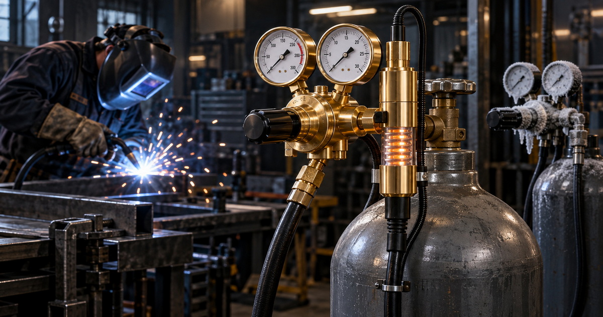
When selecting an argon flowmeter for vertical welding, buyers often compare a conventional argon flowmeter regulator with a ball-type flowmeter. In practice, these terms are sometimes used interchangeably, which can create specification mistakes during equipment sourcing. A ball-type meter is usually a type of variable-area argon flowmeter: argon lifts a floating ball inside a tapered vertical tube, and the ball position indicates the shielding-gas flow rate.
For vertical MIG and TIG welding, the decisive issue is not the label on the regulator. It is whether the gas-control assembly is correctly calibrated for argon, mounted vertically, read correctly while gas is flowing, and stable enough to maintain protective coverage around the weld pool. A poorly selected or incorrectly installed ball-type flowmeter can contribute to porosity, discoloration, excess gas use, and inconsistent weld appearance.
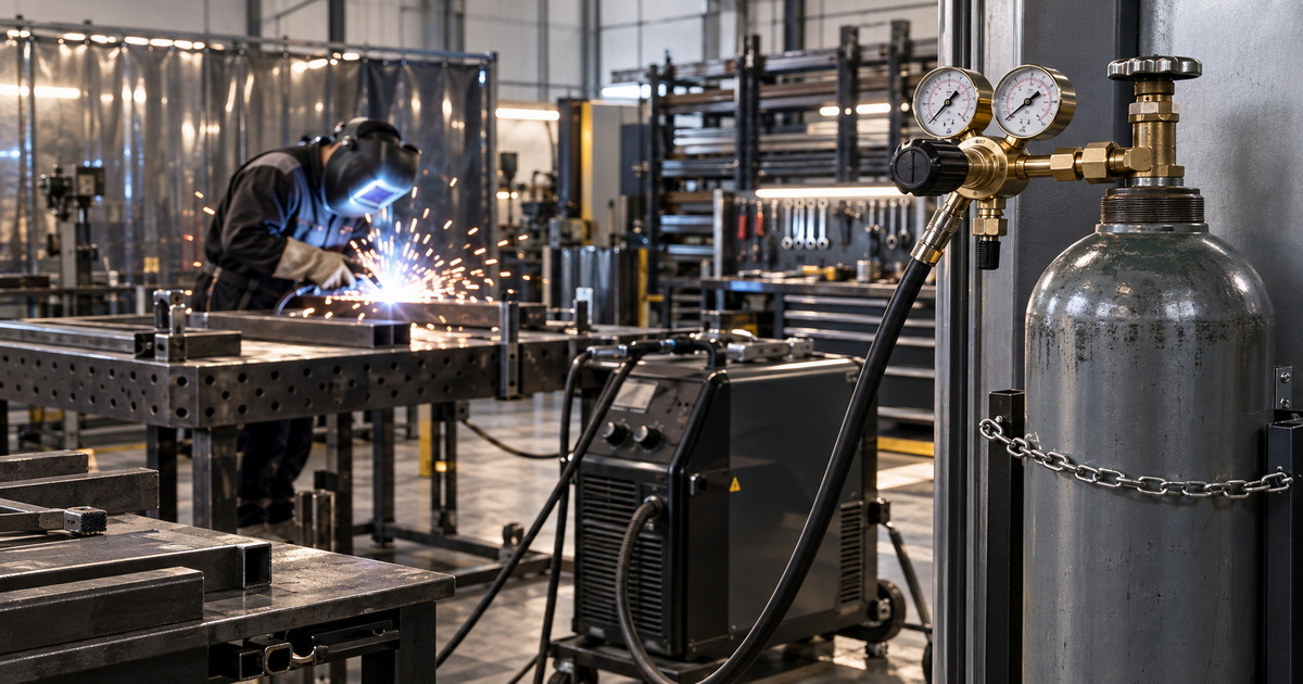
From a gas-regulator manufacturer’s perspective, the best choice for most vertical welding applications is a high-quality argon-calibrated flowmeter regulator with a correctly designed ball-type flow tube. The regulator controls cylinder pressure, while the ball-type flow tube provides direct visual confirmation of actual gas delivery.
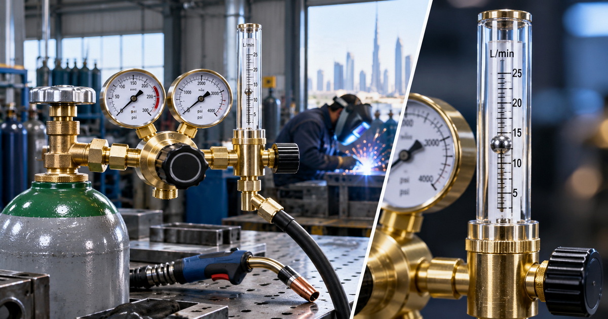
What Is the Difference Between an Argon Flowmeter and a Ball-Type Flowmeter?
The first step is to clarify the terminology.
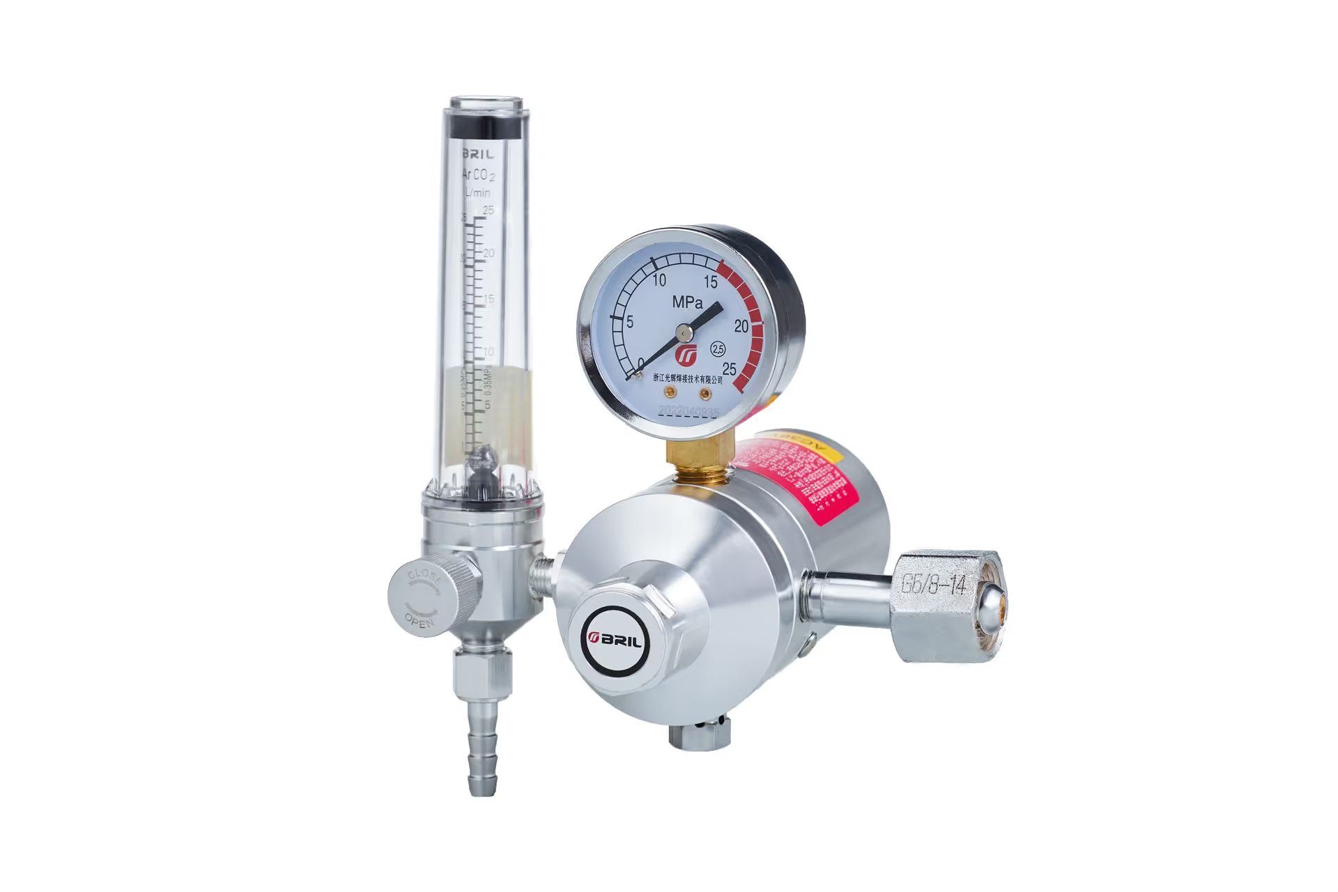
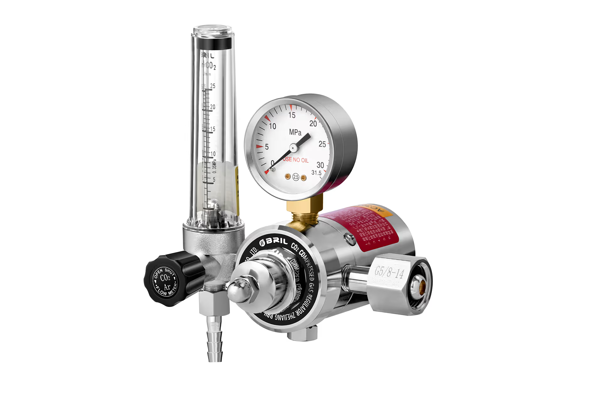
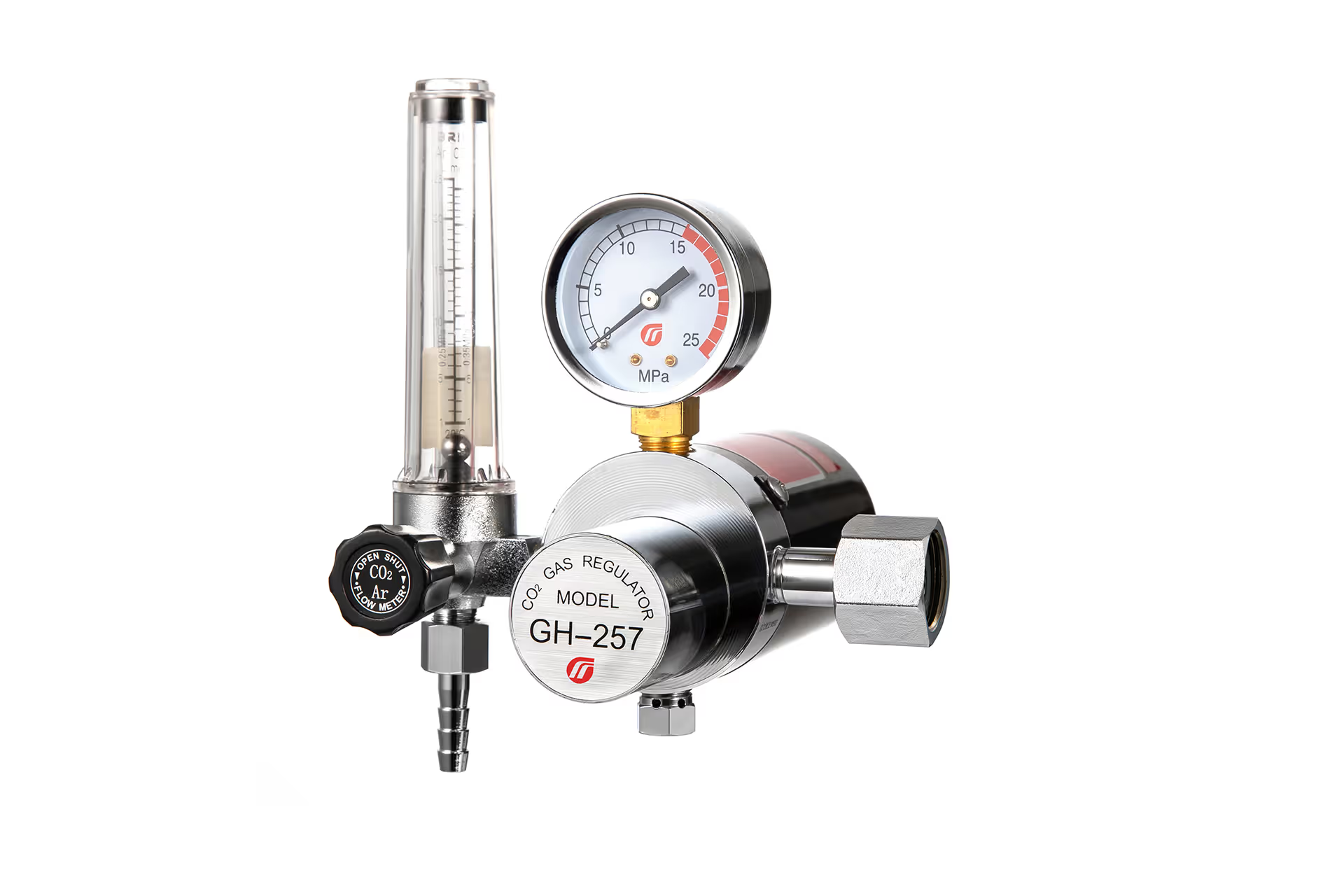
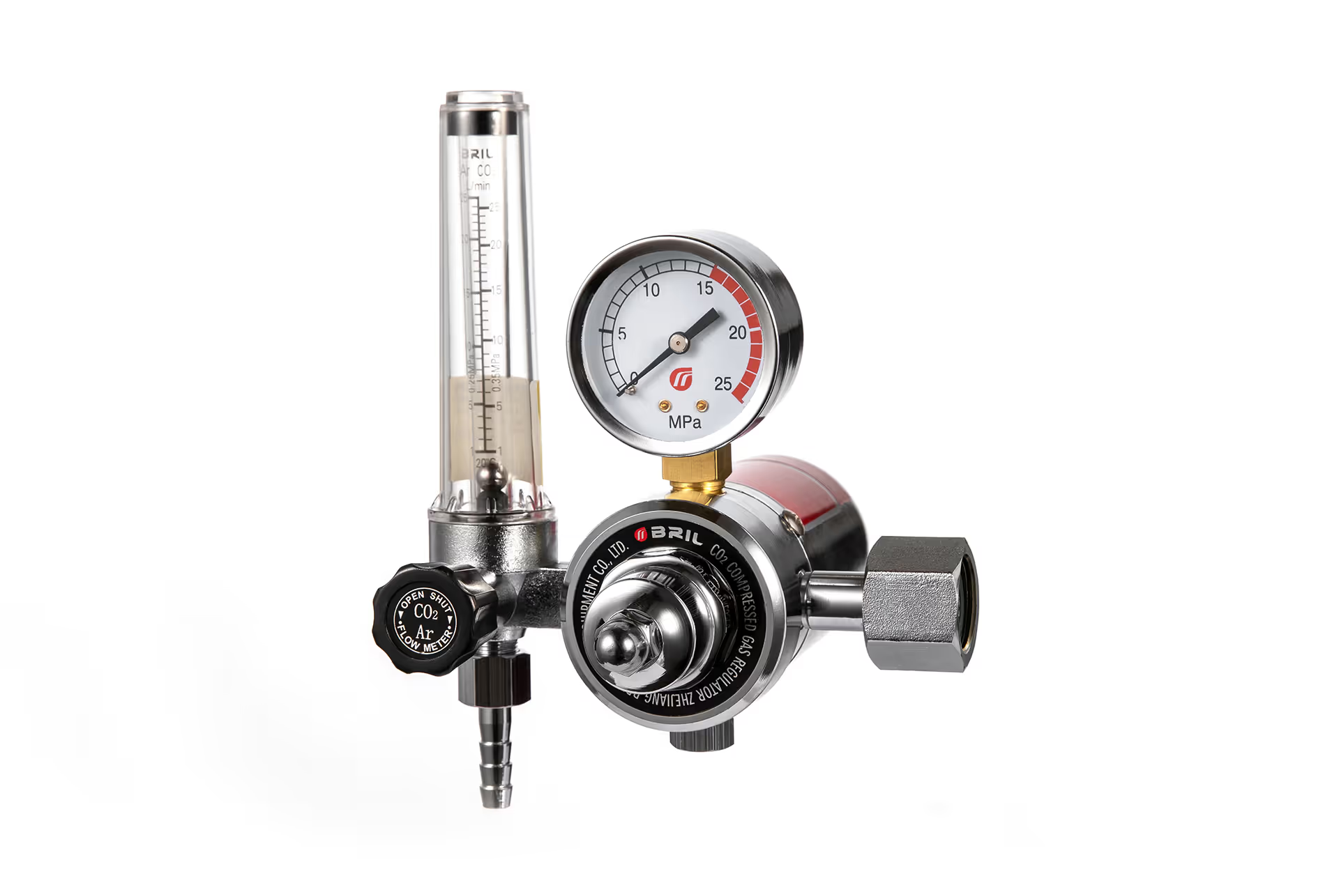
An argon flowmeter is a gas-flow control device intended for argon or compatible shielding-gas mixtures. In welding, it is commonly integrated with a pressure regulator. The regulator reduces high cylinder pressure to a safe working pressure, while the flowmeter displays and helps adjust the shielding-gas flow delivered toward the welding torch.
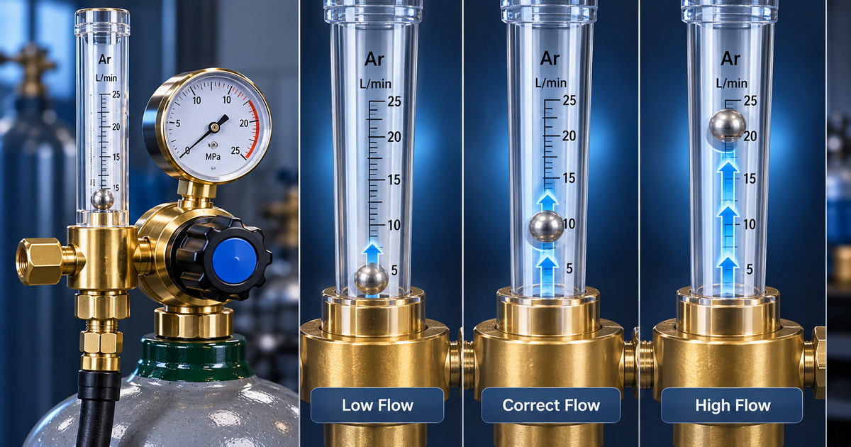
A ball-type flowmeter describes the measuring mechanism. It typically uses a transparent, tapered vertical tube containing a floating ball. As gas flow increases, the ball rises. The flow rate is read from the graduated scale—usually at the center of the ball, unless the manufacturer explicitly specifies another reference point. Variable-area flowmeters of this type are also commonly called rotameters.
Therefore, the most accurate comparison is usually:
– Argon flowmeter = the gas-specific product category or complete regulator-flowmeter assembly.
– Ball-type flowmeter = the visual measurement design used within many argon flowmeters.
– Pressure gauge regulator = a different design that estimates or sets outlet pressure rather than directly showing gas flow.
– Bobbin-type flowmeter = another variable-area flowmeter design, often read at a different point on the float.
Key takeaway
A ball-type tube is not automatically a separate alternative to an argon flowmeter. A well-designed argon ball-type flowmeter regulator can combine both functions: precise pressure reduction and easy-to-read visual flow measurement.
Argon Flowmeter vs Ball-Type Flowmeter: Technical Comparison for Vertical Welding
The table below explains the practical difference between a complete argon flowmeter regulator and the ball-type flow-indicating component typically used in that assembly.
| Comparison Factor | Argon Flowmeter Regulator | Ball-Type Flowmeter Tube | Importance for Vertical Welding |
|---|---|---|---|
| Primary function | Reduces cylinder pressure and controls shielding-gas flow | Visually indicates flow through a floating ball | Both functions are necessary for stable gas delivery |
| Gas compatibility | Should be calibrated for argon or specified argon-based mixtures | Float response depends on gas density and meter calibration | Incorrect calibration can produce inaccurate readings |
| Pressure reduction | Yes, through a diaphragm, valve, spring, seat, and body assembly | No; it does not reduce high cylinder pressure by itself | Cylinder gas must always pass through a suitable regulator first |
| Flow visibility | May include a tube, gauge, or digital indicator | Direct visual indication in a clear graduated tube | Helps operators verify flow during setup |
| Installation direction | Regulator body may vary by design | Must remain upright for accurate operation | Especially important when welding vertically or working in tight spaces |
| Reading method | Depends on meter type | Usually read at the center of the ball | Incorrect reading changes the actual setting |
| Best use | Complete MIG/TIG shielding-gas control system | A component of the complete flow-control system | Recommended as part of an argon flowmeter regulator |
| OEM/ODM options | Gauge scale, connection, pressure range, branding, packaging, flow tube and hose outlet can be customized | Ball material, tube scale, units, protective guard, and calibration may be customized | Supports local-market and distributor requirements |
A genuine flowmeter measures flow through the calibrated tube. It does not merely show pressure. This is why it is generally more useful than a basic pressure-gauge regulator when the goal is repeatable shielding-gas setup for MIG or TIG welding.
Why Vertical Welding Makes Shielding Gas Control More Demanding
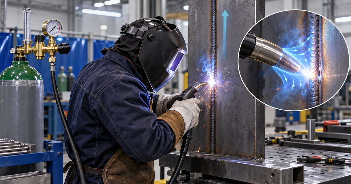
Vertical welding changes the relationship between the weld pool, arc plume, heat, and shielding gas. Hot gases rise, and the welding arc can disturb the gas envelope around the molten metal. Operators must therefore balance adequate coverage against excessive flow.
Too little argon can allow air to enter the shielding zone. Oxygen, nitrogen, moisture, and surface contamination can then contribute to visible defects or reduced weld quality. Too much flow is not automatically better. Excessive gas velocity can create turbulence and draw surrounding air into the shielding envelope.
For vertical welding, the goal is stable, laminar, application-appropriate gas coverage, not the highest possible flowmeter number.
Common symptoms of incorrect argon flow
| Symptom | Possible Gas-Control Cause | Practical Response |
|---|---|---|
| Pinholes or porosity | Low flow, gas leak, drafts, contaminated nozzle, incorrect torch distance | Inspect leaks and consumables, then adjust flow during gas delivery |
| Dark or oxidized TIG weld | Inadequate shielding, poor post-flow, excessive torch angle | Verify argon purity, cup size, nozzle position, and post-flow |
| Hissing gas and poor weld protection | Flow rate too high, turbulence around the nozzle | Reduce flow gradually and test on scrap material |
| Unstable results between operators | Inconsistent meter reading or different regulator settings | Standardize flowmeter type, scale, test procedure, and training |
| Flowmeter reading changes with installation angle | Tube not mounted vertically | Reinstall the flowmeter in a plumb vertical position |
Industry guidance consistently emphasizes that ball-type or tube flowmeters must be installed vertically and read at the designated point on the float. A tilted tube can produce a false reading because the ball no longer rises concentrically under the intended gravity-and-flow balance.
How a Ball-Type Argon Flowmeter Works
A ball-type flowmeter uses a simple but effective variable-area principle.
1. Argon enters the lower section of a tapered flow tube.
2. Gas moves upward around the floating ball.
3. Increasing flow produces greater upward force on the ball.
4. The ball rises until the upward gas force balances the ball’s weight.
5. The ball position aligns with the calibrated flow scale, typically displayed in L/min or CFH.
The wider upper area of the tapered tube allows more gas to pass around the ball as it rises. This creates a measurable relationship between ball height and flow rate.
However, accuracy depends on several factors:
– Correct gas calibration. A meter calibrated for argon should be used for argon service. Gas density affects float behavior and indicated flow.
– Vertical installation. The tube must be upright.
– Correct reading point. Standard ball floats are commonly read at the center.
– Dynamic setup. The welder should trigger gas flow before setting the meter.
– Clean internal passage. Dirt, oil, moisture, or damaged components can interfere with performance.
– Stable upstream regulation. A poor regulator can cause flow variation even when the tube itself is correctly designed.
This is why a high-quality brass regulator body, reliable valve seat, durable diaphragm, tight assembly control, and final leak testing matter as much as the visibility of the flow tube.
Which Flowmeter Is Best for Vertical MIG Welding?
For most indoor vertical MIG welding applications, a ball-type argon or argon/CO₂ flowmeter regulator is a practical and economical choice. It offers immediate visual feedback and allows the operator to adjust gas delivery while gas is actually flowing through the welding system.
However, “best” depends on the job conditions.
Choose an argon ball-type flowmeter regulator when:
– You need a direct and visible indication of shielding-gas flow.
– You perform MIG, MAG, or TIG welding with argon or argon-based mixtures.
– You need a common, serviceable design for workshop, fabrication, or distributor applications.
– Your operators must make quick setup adjustments across different torch sizes or nozzle configurations.
– You want to reduce wasted gas caused by pressure-based guesswork.
– The flowmeter can be mounted upright and protected from impact.
Consider additional flow verification when:
– Welding takes place outdoors or near strong drafts.
– Very long torch leads, damaged liners, leaks, or restricted hoses may affect delivery.
– The work involves critical stainless steel, aluminum, aerospace, food-grade, pharmaceutical, or high-purity applications.
– Multiple torches operate from manifolds or centralized gas systems.
– You need to verify flow at the torch nozzle rather than only at the regulator outlet.
A portable nozzle flow checker can confirm the gas reaching the torch. This is especially useful during troubleshooting because the regulator flowmeter is positioned upstream of the hose, solenoid, and torch.
Recommended Argon Flow Settings for Vertical Welding
There is no universal argon flow setting. Correct flow depends on welding process, wire diameter, tungsten size, nozzle or cup size, torch angle, material, joint design, gas type, indoor airflow, and welding parameters.
For GTAW, the American Welding Society has cited typical manual-torch argon flow ranges of approximately 10–25 SCFH, or 5–12 L/min, while helium typically requires higher flow. These values are starting references, not a substitute for qualified welding procedures.
For vertical-position welding, practical welding guidance often recommends starting slightly higher than flat-position flow, then confirming weld quality and avoiding turbulence. One current industry guide suggests increasing vertical-position flow by approximately 5–10 CFH compared with flat-position settings, while also warning against overly high indoor flow that can create turbulence.
Practical starting ranges
| Welding Scenario | Suggested Starting Point | Adjustment Considerations |
|---|---|---|
| TIG welding with pure argon, standard cup | 10–20 CFH | Start lower for smaller cups and short arc lengths; increase cautiously for drafts or larger cups |
| MIG welding with argon/CO₂ mix, indoor | 20–25 CFH | Adjust for nozzle diameter, stickout, torch angle, and local air movement |
| Vertical-up welding | Start from qualified flat setting; assess a small increase if coverage is weak | Maintain close nozzle-to-work distance and avoid excessive gas velocity |
| Drafty work area | Improve shielding first | Use screens, check leaks, and make controlled flow changes rather than immediately maximizing flow |
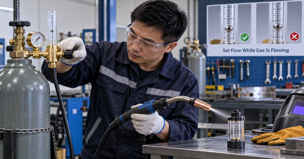
Expert Setup Procedure for Vertical Welding Argon Flowmeters
As a manufacturer serving welding-equipment brands, wholesalers, and industrial distributors, we recommend that every operator and quality team use a repeatable setup process.
1. Confirm the gas and connection standard
Verify that the regulator and flowmeter are approved for the actual gas—pure argon, argon/CO₂ mix, helium blend, nitrogen, or another specified gas. Confirm the cylinder valve connection, outlet thread, hose size, and local market standard before installation.
Never assume that a regulator is compatible simply because it looks similar to another model.
2. Secure the cylinder and inspect the equipment
Keep the cylinder upright and secured. Inspect the regulator inlet seal, threads, gauges, hose, flowmeter tube, torch fittings, and nozzle. Replace cracked hoses, damaged O-rings, contaminated diffusers, or broken flow tubes.
3. Install the ball-type flowmeter vertically
Ensure that the transparent tube is truly upright. A ball flowmeter depends on gravity. If the assembly is tilted, the ball can contact the tube wall and display a misleading value.
4. Open the cylinder valve carefully
Open the cylinder valve in accordance with the gas supplier’s and equipment manufacturer’s safety guidance. Check for leaks using an approved leak-detection method. Never use an open flame to test for a gas leak.
5. Purge the system
Trigger gas flow briefly to displace air from the hose and torch. This is particularly important after cylinder replacement, hose removal, or extended equipment downtime.
6. Set the flow under live gas delivery
With gas flowing, adjust the control valve slowly until the ball stabilizes at the desired flow value. Read the center of the ball unless the scale identifies a different reading point.
7. Run a test weld and inspect the bead
Use scrap material with the same base metal, filler, joint position, and gas type whenever possible. Watch for porosity, oxidation, excessive spatter, unstable arc behavior, or visibly turbulent gas flow.
8. Record the approved setting
For repeat production, document the gas type, regulator model, flow setting, nozzle size, torch distance, welding position, and relevant WPS parameters. This supports operator consistency and helps distributors provide better technical after-sales support.
Manufacturing Factors That Affect Flowmeter Reliability
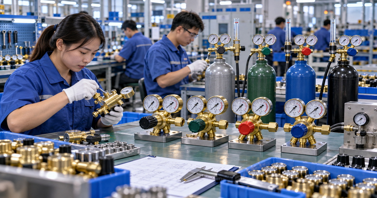
From an OEM and ODM sourcing viewpoint, two flowmeters may look nearly identical but perform differently over time. Buyers should evaluate the complete gas-control system rather than focusing only on the transparent tube.
Critical quality-control points
– Brass material selection: The body and key fittings should use suitable brass material with controlled machining quality and corrosion resistance.
– Thread accuracy: Inlet and outlet threads must match target-market specifications and engage smoothly without cross-threading.
– Diaphragm and seal compatibility: Internal elastomers and diaphragms must suit the designated gas service and working environment.
– Flow calibration: The scale must correspond to the intended gas and unit system, such as L/min or CFH.
– Tube clarity and impact protection: The tube should remain readable and protected against workshop damage.
– Leak testing: The finished assembly should undergo defined leak checks.
– Pressure stability: The regulator should maintain usable outlet performance as cylinder pressure decreases.
– Gauge readability: Scale range, printing clarity, zero return, and vibration resistance influence operator accuracy.
– Traceability: OEM customers benefit from batch identification, inspection records, and retained samples.
For buyers ordering private-label regulators, the technical specification should clearly state the gas service, inlet fitting, outlet connection, gauge range, flow range, units, flowmeter type, brand artwork, packaging, and required tests. A two-gauge appearance alone does not prove that a regulator uses a true two-stage pressure-reduction mechanism; buyers should request design information and performance documentation. [chinesewelding]
Final Recommendation: Choose a Complete Argon Flowmeter Regulator
For vertical welding, the strongest solution is usually not “argon flowmeter versus ball-type flowmeter.” It is a properly engineered argon flowmeter regulator that uses a calibrated ball-type flow tube.
This combination gives operators what they need:
– Stable reduction of high cylinder pressure.
– Visible flow adjustment for argon shielding gas.
– A practical way to standardize MIG and TIG welding setup.
– Better control of gas use and weld consistency.
– A familiar format for distributors, repair shops, fabricators, and OEM welding-machine brands.
For demanding industrial applications, buyers should also validate actual flow at the torch, establish qualified procedures, and select a manufacturer able to provide material control, leak testing, calibration support, customized connections, branding, packaging, and documented quality inspection.
Need an OEM or ODM argon flowmeter regulator for vertical welding? Send your target market, gas type, cylinder connection, flow range, pressure range, gauge units, branding requirements, and annual quantity. Our engineering team can help configure a reliable brass argon regulator or ball-type flowmeter regulator for your welding equipment, distribution, or private-label program.
FAQ
1. Is an argon flowmeter the same as a ball-type flowmeter?
Not exactly. An argon flowmeter refers to a device or regulator assembly designed to control and indicate argon flow. A ball-type flowmeter refers to the measurement mechanism, where a floating ball rises inside a tapered vertical tube. Many argon flowmeter regulators use a ball-type tube.
2. Why must a ball-type flowmeter be installed vertically?
The float ball rises because gas flow pushes it upward against gravity. If the tube is tilted, the ball can move off-center or rub against the wall, which can produce an inaccurate reading. Keep the tube upright for reliable operation.
3. Where should I read the ball on an argon flowmeter?
For a standard ball-type welding flowmeter, read the flow rate at the center of the ball, unless the manufacturer’s printed scale or manual specifies another reference point. Different float designs can have different reading conventions.
4. What argon flow rate should I use for vertical TIG welding?
A common starting range for manual TIG welding with argon is approximately 10–25 CFH, or 5–12 L/min. Actual settings must be confirmed based on cup size, tungsten, torch angle, joint design, material, drafts, and the applicable welding procedure.
5. Can excessive argon flow cause porosity?
Yes. More gas is not always better. Excessive flow can create turbulence around the nozzle and entrain surrounding air, which may degrade shielding. First inspect for leaks, drafts, contamination, and torch-position issues before increasing flow.
6. Can I use an argon-calibrated flowmeter for CO₂ or helium?
You should use a flowmeter calibrated for the actual gas whenever possible. Gas density affects float behavior. Argon meters can be suitable for argon and some argon-based blends, but readings may be inaccurate with pure CO₂ or helium-containing mixtures unless the manufacturer provides correction data.
7. How can I verify actual gas flow at the welding torch?
Use a portable nozzle flow checker. Place it vertically over the MIG nozzle or TIG cup, activate gas flow without striking an arc, and read the floating ball. This verifies delivery at the torch rather than only at the regulator.
References
2. [CIGWELD BlueVenom XF190 Operating Manual—flow adjustment guidance and center-of-ball reading]
3. [WeldIndex—Welding gas regulators and flowmeters guide]
4. [Technoweld—GMAW gas shielding and correct flowmeter orientation/reading practices]
6. [Miller/Cyberweld—Argon flowmeter regulator and self-centering ball guide information]
7. [ESAB portable nozzle flow checker—verifying flow at the torch]
Hot Tags: Argon Flowmeter Regulator, Ball-Type Flowmeter, Welding Gas Flowmeter, Argon Gas Regulator, MIG TIG Flowmeter Regulator, Argon CO₂ Regulator, Welding Shielding Gas Regulator, Brass Gas Regulator, OEM Welding Gas Regulator, Industrial Gas Flow Control