Content Menu
● What Does Fluctuating Argon Flow Actually Mean?
>> Pressure and Flow Are Different Measurements
● Common Causes of Argon Flow Fluctuation During TIG Welding
>> 1. Startup Gas Surge From Pressurized Hoses
>> 2. Incorrect Flowmeter Setup or Reading
>> 3. Leaking Connections or Damaged Hoses
>> 4. Hose Restrictions and Torch Blockages
>> 5. Regulator Supply Pressure Effect
>> 6. Regulator Droop, Damage, or Seat Leakage
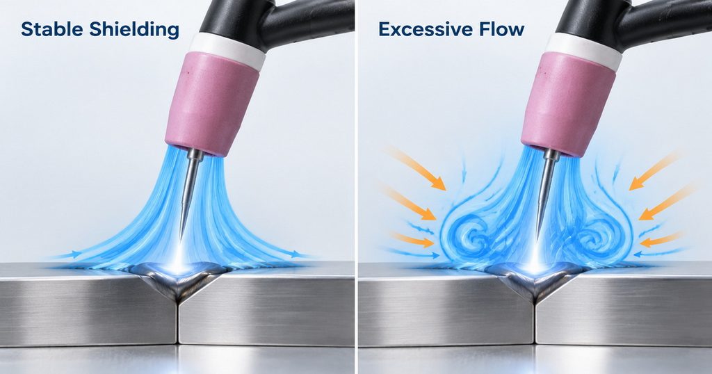
>> 7. Drafts and Excessive Gas Flow
● What Argon Flow Rate Should You Use for TIG Welding?
● A Step-by-Step Argon Flow Troubleshooting Procedure
>> Step 1: Establish a Safe Baseline
>> Step 2: Observe Flow Without an Arc
>> Step 3: Compare Supply and Torch Delivery
>> Step 4: Inspect and Isolate the Gas Path
● Diagnose the Problem by Its Timing
● Single-Stage vs. Dual-Stage Argon Regulators
● How Buyers Can Specify More Reliable Argon Gas Control
>> A Useful Production Validation Record
● Specify Stable Argon Delivery for Your Next Project
>> 1.Why Does My Argon Flowmeter Ball Bounce?
>> 2.Can Too Much Argon Cause TIG Weld Porosity?
>> 3.Should I Set Argon Flow With the Gas Running?
>> 4.Will a Dual-Stage Regulator Stop Every Flow Fluctuation?
>> 5.Why Is Flow Stable at the Cylinder but Poor at the Torch?
>> 6.Does Pulsed TIG Require Pulsed Argon Flow?
Argon flow fluctuates during TIG welding because pressure, restrictions, or gas demand change somewhere between the cylinder and the torch. Common causes include startup gas surges, incorrect flowmeter settings, leaking connections, restricted hoses, regulator instability, and shielding disturbed by drafts. The essential first step is to distinguish actual flow fluctuation from a misleading instrument reading or poor gas coverage.
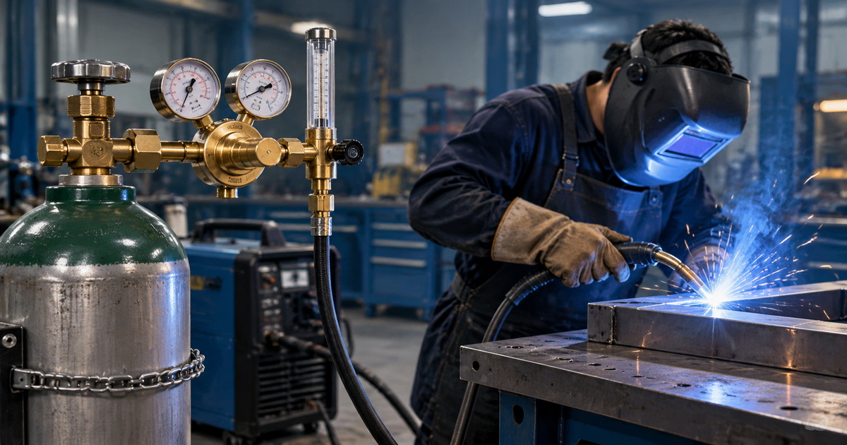
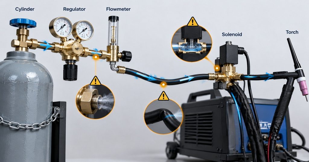
From a gas-control manufacturing perspective, replacing the regulator should not be the first response. A reliable diagnosis follows the entire gas path: cylinder, regulator, flowmeter, hose, machine solenoid, and torch. Understanding when the fluctuation occurs usually reveals where to investigate.
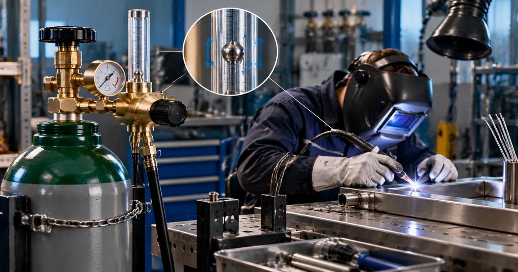
What Does Fluctuating Argon Flow Actually Mean?
Three different problems can look similar during welding:
– The flowmeter ball rises and falls while gas is flowing.
– Gas delivery surges at startup or changes during a weld.
– The weld develops oxidation or porosity despite an apparently steady flow reading.
These symptoms require different solutions. A stable reading at the cylinder does not prove that shielding remains effective around the weld pool. Conversely, brief ball movement when the gas valve opens does not automatically indicate regulator failure.
Start by recording whether the problem occurs at arc initiation, continuously, after moving the torch, or as the cylinder empties.
Pressure and Flow Are Different Measurements
A regulator controls delivery pressure. A flowmeter indicates gas flow under specified operating conditions.
Pressure appears in units such as bar or psi. Flow appears in liters per minute, abbreviated L/min, or cubic feet per hour, abbreviated CFH.
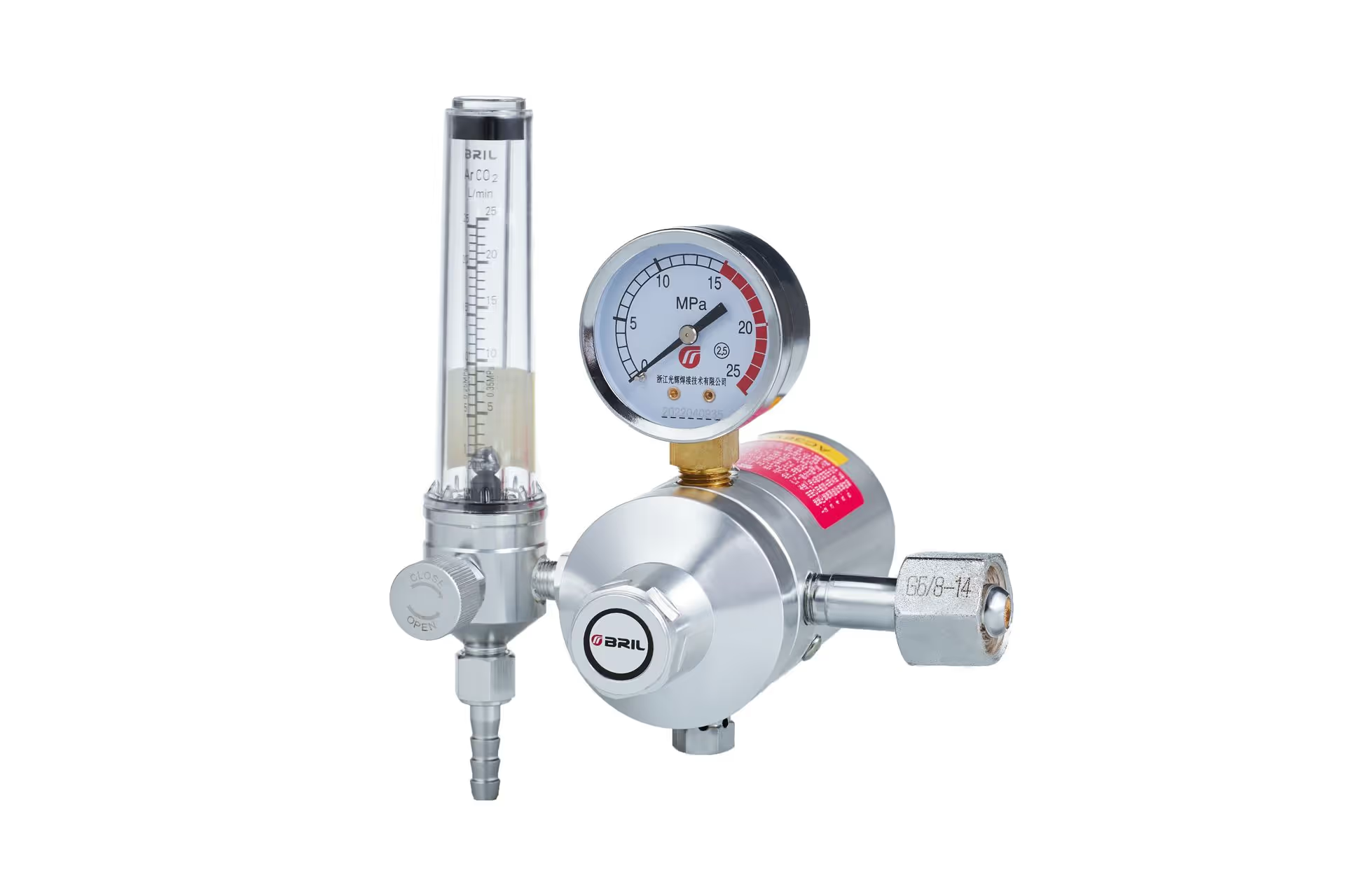
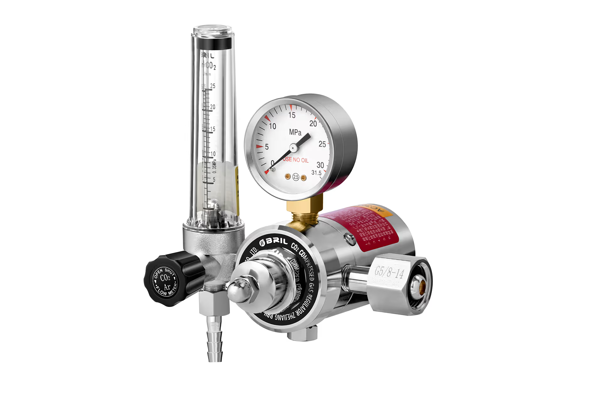
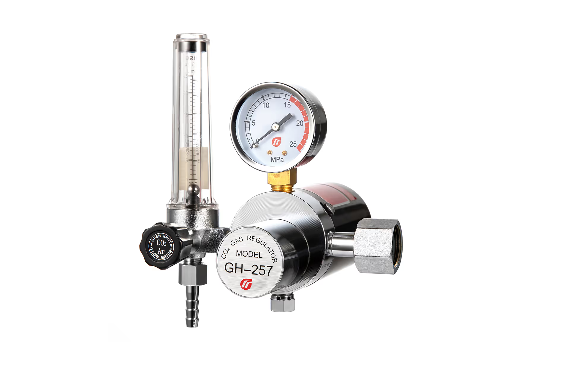
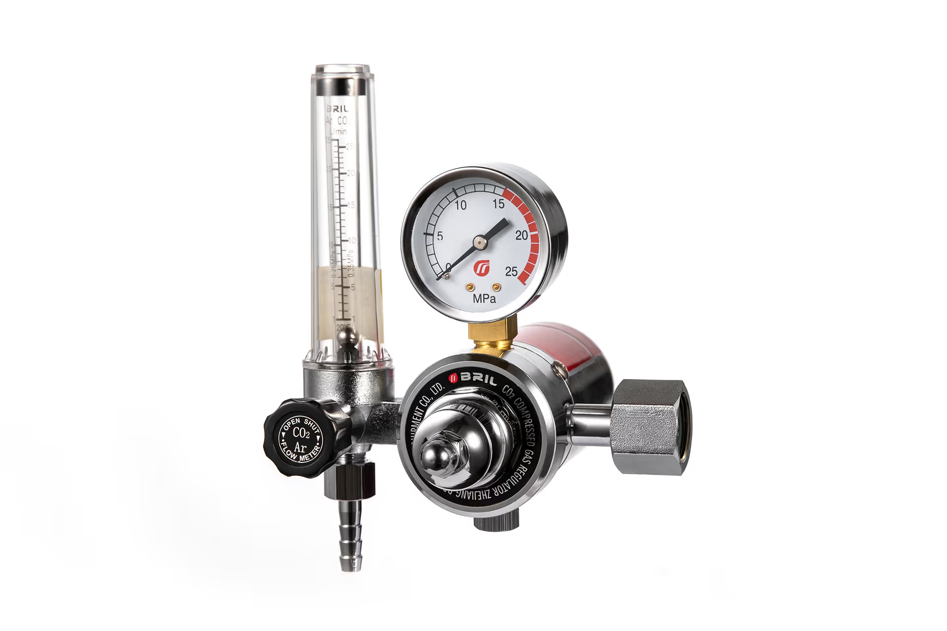
A pressure gauge with a flow-calibrated scale generally infers flow through a specified restriction. Changes to that restriction can affect the relationship between the indicated value and actual delivery.
Common Causes of Argon Flow Fluctuation During TIG Welding
1. Startup Gas Surge From Pressurized Hoses
When the machine’s gas solenoid closes, gas upstream can remain pressurized. At the next start, that stored gas discharges before the system settles into steady flow.
Longer hoses can store more gas, making the initial surge more noticeable. Excessive velocity at the cup may temporarily disturb shielding rather than improve it.
Practical corrections include:
– Keeping supply hoses no longer than necessary.
– Using the specified regulator and flow-control arrangement.
– Setting preflow according to the welding equipment instructions.
– Considering a compatible surge-control device where appropriate.
Do not eliminate necessary preflow simply to reduce consumption. Preflow helps establish shielding before the arc starts.
2. Incorrect Flowmeter Setup or Reading
Most conventional variable-area flowmeters need the specified mounting orientation, commonly vertical. Read the float at the reference point identified by its manufacturer; not every float uses the same reading convention.
The meter must also match the gas and its specified operating pressure. An argon scale should not be treated as universally accurate for helium or other gases.
Set flow while gas is moving through the actual welding circuit, using the machine’s gas-test function where available. A setting made with the solenoid closed does not establish operating flow.
3. Leaking Connections or Damaged Hoses
Loose fittings, damaged seals, cracked hoses, and worn torch connections can reduce gas reaching the cup.
A cylinder-mounted meter may still show flow because it measures gas leaving that part of the system—not exclusively gas arriving at the torch.
Inspect connections with an approved leak-detection solution compatible with the equipment. Follow the manufacturer’s procedure, and never use a flame.
Close the cylinder and safely depressurize the system before replacing components. Do not compensate for leakage by opening the flow control further.
4. Hose Restrictions and Torch Blockages
A kinked hose, crushed section, contaminated fitting, or obstructed torch passage increases resistance.
Intermittent problems often appear when the torch moves. If flow changes as the cable assembly bends, inspect the hose routing and torch lead before adjusting the regulator.
Check:
– Hose bends and compression points.
– Quick-connect fittings and internal valves.
– Torch assembly and seal condition.
– Gas-lens screens and consumable cleanliness.
A contaminated gas lens can also disrupt gas distribution even when total flow appears acceptable.
5. Regulator Supply Pressure Effect
Some regulators change outlet pressure as cylinder pressure decreases. This behavior is called supply pressure effect.
In many conventional unbalanced pressure-reducing designs, falling inlet pressure causes outlet pressure to rise. Therefore, “the cylinder is getting empty” does not always mean that flow must gradually decrease.
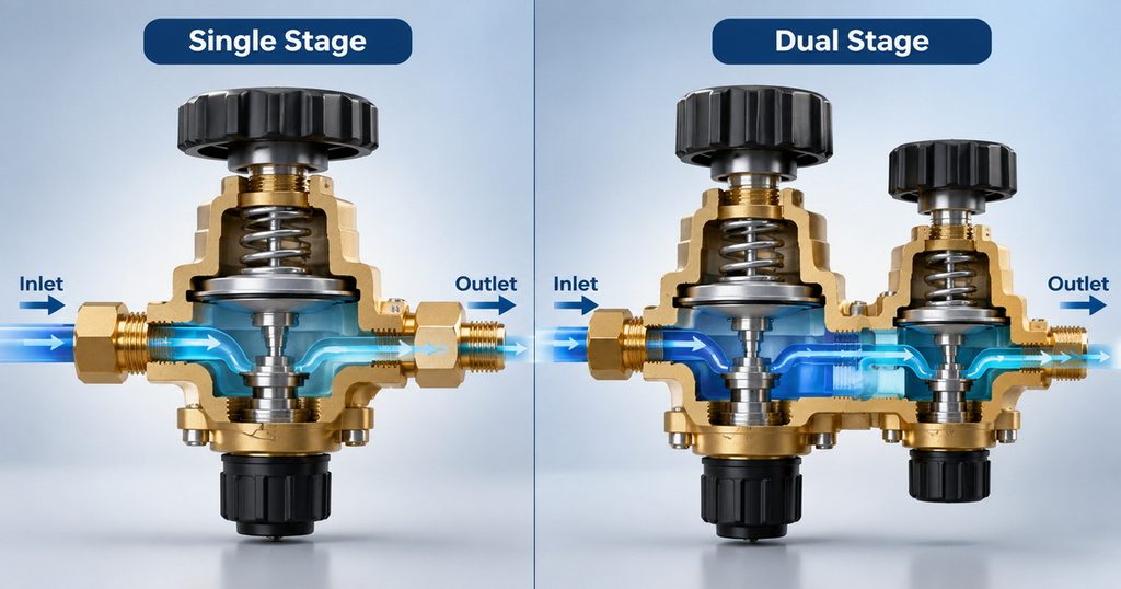
A dual-stage regulator reduces pressure in two steps and generally limits this influence. However, it cannot correct downstream leaks, an unsuitable flowmeter, or poor torch shielding.
Near depletion, insufficient inlet pressure eventually prevents the regulator from maintaining its required outlet conditions.
6. Regulator Droop, Damage, or Seat Leakage
Droop means that outlet pressure decreases as downstream demand increases. It becomes relevant when a regulator is undersized or when several users share a supply.
Seat leakage is different. Gas passes an inadequately sealing seat, potentially causing outlet pressure to keep rising after downstream flow stops. This is often called creep.
A normal initial transition to shutoff pressure should not be confused with a continuing pressure rise. Suspected creep requires inspection by qualified personnel, not repeated adjustment during production.
7. Drafts and Excessive Gas Flow
Sometimes the gas supply remains stable, but shielding does not.
Fans, open doors, extraction airflow, and outdoor wind can move argon away from the weld pool. Increasing flow excessively may create turbulence and draw surrounding air into the shielding stream.
Check the environment, cup selection, torch angle, and electrode extension alongside the regulator. Preserve required ventilation; reposition shielding or extraction arrangements safely rather than disabling fume control.
What Argon Flow Rate Should You Use for TIG Welding?
There is no single correct setting for every TIG application.
Miller’s troubleshooting guidance gives 15–20 CFH as a useful starting range for many conventional setups. This is approximately 7–9.4 L/min. Its broader shielding guidance describes a wider application-dependent range.
Use the torch and consumable manufacturer’s recommendations and any applicable welding procedure.
| Application condition | Recommended approach |
|---|---|
| Standard cup in a sheltered workspace | Begin with the recommended baseline and verify coverage |
| Larger cup or extended tungsten | Follow gas-lens and torch guidance; validate the setup |
| Draft near the joint | Control the disturbance before increasing flow |
| Long supply hose | Investigate startup surge and pressure losses |
| Shared gas supply | Check available capacity during simultaneous demand |
The objective is adequate, repeatable coverage—not the highest possible flow setting.
A Step-by-Step Argon Flow Troubleshooting Procedure
Step 1: Establish a Safe Baseline
Secure the cylinder upright and confirm that the regulator, connections, hoses, and gas are suitable for the application.
Use adequate ventilation. Argon can displace oxygen, particularly where gas accumulates in poorly ventilated spaces.
Record cylinder pressure, selected flow, hose length, cup size, and when the symptom occurs.
Step 2: Observe Flow Without an Arc
Use the machine’s approved gas-test function.
Watch the initial response and the steady reading separately. A brief startup jump suggests a different problem from continuous oscillation.
Do not confuse programmed preflow and postflow with an unintended gas-control fault.
Step 3: Compare Supply and Torch Delivery
Use a suitable torch-end flow checker according to its instructions, with the arc off.
Compare results under repeatable conditions. The instruments may differ in calibration, reference conditions, and accuracy, so do not expect perfect numerical agreement.
A substantial, repeatable discrepancy warrants investigation for leakage, restriction, or incompatible measurement conditions.
Step 4: Inspect and Isolate the Gas Path
Check accessible fittings, hoses, machine connections, and torch components.
Change one variable at a time. If replacing a component for diagnosis, use an approved, compatible part and follow isolation and depressurization procedures.
Step 5: Verify the Repair
Repeat the gas-flow check and make a test weld using the intended setup.
Evaluate shielding, tungsten condition, and weld appearance. Where production specifications require inspection or testing, appearance alone is not sufficient acceptance evidence.
Diagnose the Problem by Its Timing
The timing of a fluctuation is often more informative than its magnitude.
| Observed pattern | Likely investigation area | First practical check |
|---|---|---|
| Strong surge only at startup | Stored gas and hose pressurization | Review hose length and preflow |
| Repeated fluctuation during steady flow | Supply, regulator, or restriction | Observe inlet and outlet behavior |
| Change when the torch moves | Hose, connection, or torch lead | Inspect bending and routing |
| Gradual change over cylinder life | Supply pressure effect | Compare readings at different cylinder pressures |
| Stable meter but oxidized weld | Local shielding or downstream problem | Check drafts, torch delivery, and consumables |
| Change when another station starts | Shared supply capacity | Test simultaneous demand |
These patterns guide troubleshooting; they are not definitive diagnoses by themselves.
Single-Stage vs. Dual-Stage Argon Regulators
A correctly selected single-stage regulator can serve many manual TIG welding applications well.
A dual-stage regulator becomes more attractive when the process needs consistent delivery across a substantial change in cylinder pressure, particularly during longer production runs.
| Selection factor | Single-stage regulator | Dual-stage regulator |
|---|---|---|
| Pressure reduction | One stage | Two sequential stages |
| Cylinder-pressure influence | More dependent on design | Generally reduced |
| Appropriate applications | Many routine welding tasks | Processes needing tighter pressure consistency |
| Important limitation | May require more readjustment | Does not independently guarantee constant torch flow |
Two gauges do not mean two stages. A regulator may have cylinder-pressure and delivery-pressure gauges while still using only one pressure-reduction stage.
For procurement, request performance information rather than relying on gauge count or product appearance.
How Buyers Can Specify More Reliable Argon Gas Control
For overseas brands, distributors, and equipment manufacturers, “brass argon regulator” is not a complete purchasing specification.
High-quality brass and precision machining matter, but stable performance also depends on seat design, sealing materials, assembly cleanliness, flow capacity, and inspection.
An effective specification should identify:
– Gas service, maximum inlet pressure, and outlet requirements.
– Required flow range and measurement units.
– Flowmeter calibration conditions.
– Cylinder connection and destination-market compatibility.
– Permitted pressure variation under defined conditions.
– Leak-test methods, acceptance criteria, and traceability.
– Applicable product standards and required documentation.
Ask whether a supplier can demonstrate performance at high, intermediate, and low inlet pressures—not merely provide a static gauge photograph.
For OEM and ODM projects, define the complete operating envelope before approving samples. Avoid assuming that one regulator platform is interchangeable across argon, oxygen, acetylene, propane, nitrogen, and CO₂ services.
A Useful Production Validation Record
A simple test record can make troubleshooting more repeatable:
1. Record equipment configuration and initial cylinder pressure.
2. Measure steady flow through the approved circuit.
3. Repeat several start-stop cycles.
4. Observe behavior during normal hose movement.
5. Check representative simultaneous demand, if applicable.
6. Document results and corrective actions.
This is a proposed validation framework, not a substitute for a product standard or qualified acceptance procedure.
Specify Stable Argon Delivery for Your Next Project
For an OEM or ODM argon regulator project, send us your cylinder connection, inlet-pressure range, required flow, torch configuration, target market, and testing requirements.
Our manufacturing focus includes precision-machined brass components, pressure control, quality inspection, and customized industrial gas solutions. We can discuss a suitable regulator and flow-control configuration, with applicable standards and documentation defined for your project.
Frequently Asked Questions
1.Why Does My Argon Flowmeter Ball Bounce?
A brief jump when the solenoid opens may reflect startup surge. Persistent movement can indicate changing pressure, intermittent restrictions, or unsuitable meter installation. Check steady-flow behavior before replacing parts.
2.Can Too Much Argon Cause TIG Weld Porosity?
Yes. Excessive flow can create turbulence that introduces surrounding air into the shielding stream. Check coverage and environmental conditions instead of assuming more gas always provides better protection.
3.Should I Set Argon Flow With the Gas Running?
Yes. Set and verify flow while gas passes through the intended welding circuit, following the equipment instructions. A closed solenoid prevents a meaningful operating-flow adjustment.
4.Will a Dual-Stage Regulator Stop Every Flow Fluctuation?
No. It generally reduces the influence of changing inlet pressure. It does not repair leaks, remove restrictions, correct calibration errors, or protect the weld from drafts.
5.Why Is Flow Stable at the Cylinder but Poor at the Torch?
Gas may escape downstream, encounter a restriction, or become poorly distributed through the torch. A suitable torch-end check helps distinguish delivery problems from local shielding problems.
6.Does Pulsed TIG Require Pulsed Argon Flow?
Not automatically. Pulsed TIG normally refers to changing welding current. Do not assume the gas should pulse unless the equipment specifically provides a programmed gas-control function.
References
1. – Miller Electric. “Common TIG Welding Problems.” Practical guidance on shielding gas selection, the 15–20 CFH starting range, excessive flow, and leak checks. [millerwelds]
2. – Miller Electric. “Best Practices for Proper Shielding Gas in TIG Welding.” Explains turbulence, application-dependent flow, gas lenses, and startup surges associated with long gas lines. [millerwelds]
3. – Swagelok. “Managing Supply Pressure Effect in Regulators.” Explains inlet-pressure dependency and how two-stage pressure reduction limits its effect. [swagelok]
4. – Swagelok. “Pressure Regulators: Tech Tip Videos.” Defines droop and discusses regulator flow behavior. [safst.swagelok]
5. – Harris Products Group. “Life Expectancy of Compressed Gas Regulators.” Discusses internal leakage, including regulator creep or crawl. [harrisproductsgroup]
6. – Miller Electric. “Heavy-Duty Flowmeters and Flowmeter Regulators.” Product documentation illustrating specified operating pressures, gas scales, and flowmeter design differences. [contenthub.itwwelding]
Hot Tags: Argon Regulator, Argon Gas Regulator, TIG Welding Gas Regulator, Argon Flowmeter Regulator, Dual Stage Argon Regulator, Industrial Gas Regulator, Welding Gas Flowmeter, Brass Gas Regulator, OEM Gas Regulator Manufacturer, Argon Regulator Supplier