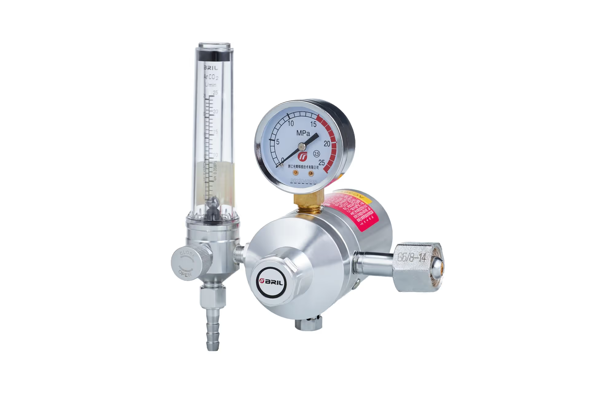
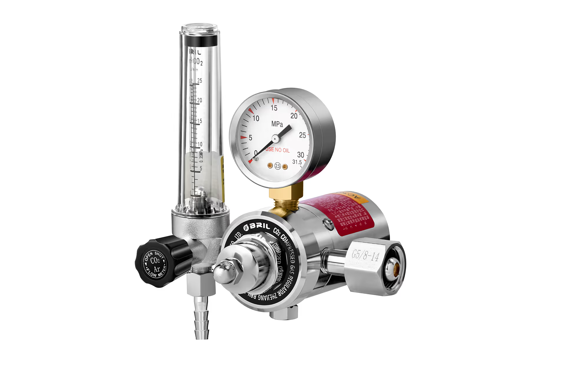
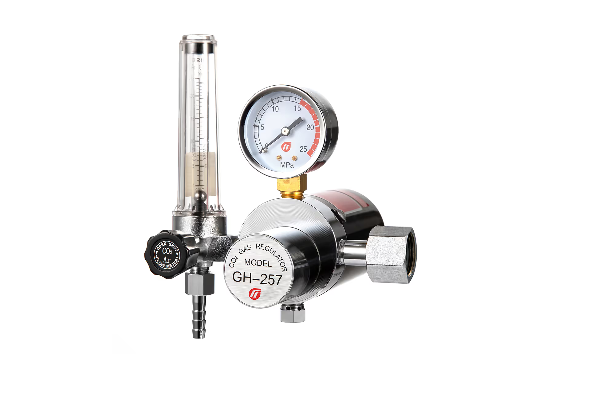
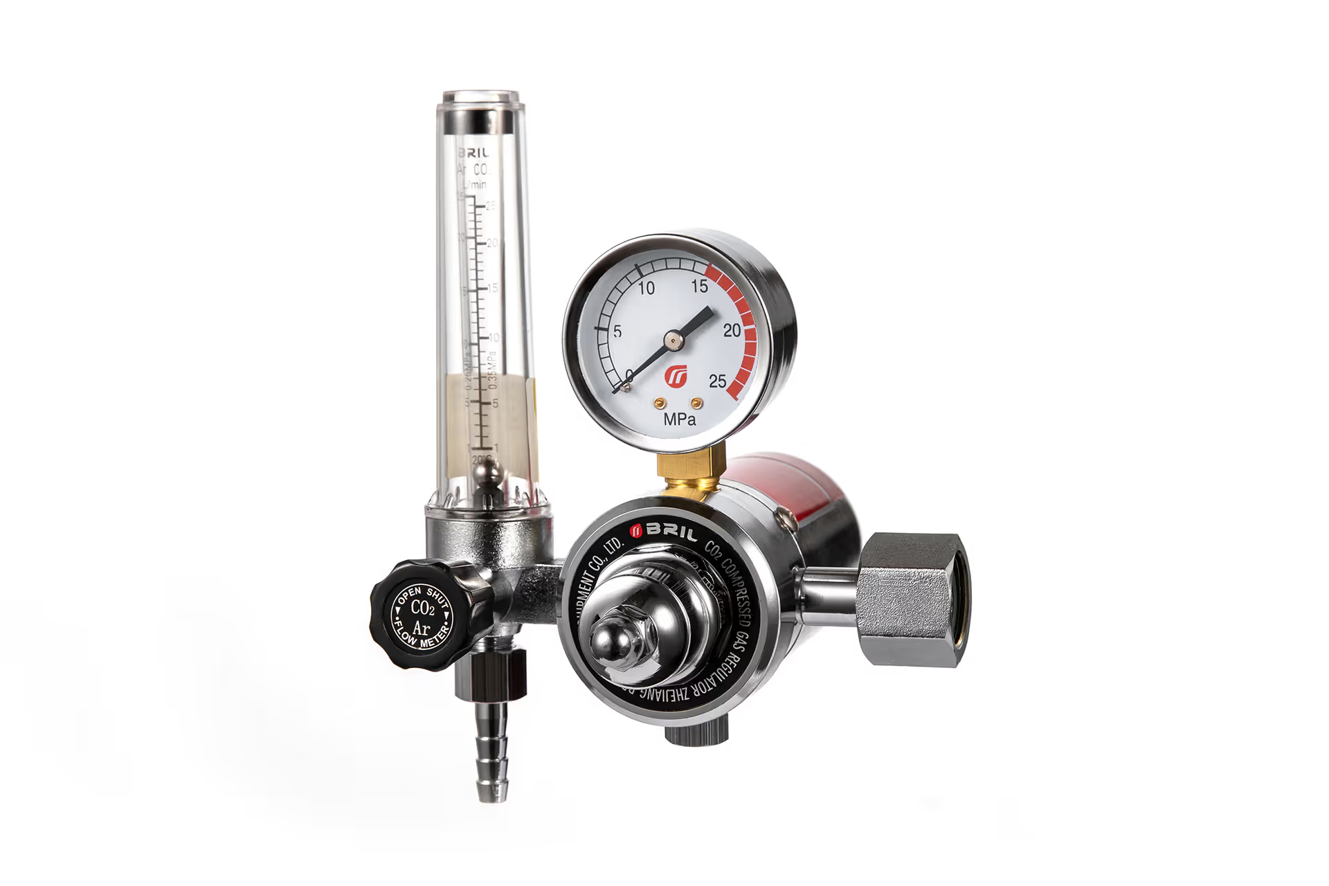
Content Menu
● Is the Gas Flow Really Dropping?
>> Pressure and Flow Are Different Measurements
>> An Initial Surge Can Look Like a Flow Drop
● Seven Reasons Gas Flow Drops During MIG Welding
>> 1. The Gas Supply Cannot Sustain Demand
>> 2. CO₂ Cooling Restricts the Regulator
>> 3. Leaks Divert Gas Before It Reaches the Torch
>> 4. Hoses and Torch Components Restrict Delivery
>> 5. The Regulator Is Undersized or Unstable Under Load
>> 6. The Solenoid Valve Does Not Open Correctly
>> 7. The Flow Reading Is Misleading
● How Much Shielding Gas Does MIG Welding Need?
● A Practical MIG Gas-Flow Troubleshooting Procedure
>> Step 1: Make the Inspection Safe
>> Step 2: Establish a Flowing Baseline
>> Step 3: Compare Supply Indication With Nozzle Delivery
>> Step 4: Inspect the Entire Delivery Path
>> Step 5: Reproduce the Actual Operating Pattern
>> Step 6: Escalate With Useful Evidence
● Diagnose the Problem by Its Timing
● Heated or Dual-Stage: Which Regulator Solves the Problem?
>> Choose Heated CO₂ Regulation for a Thermal Limitation
>> Choose Dual-Stage Regulation for Inlet-Pressure Stability
● What Overseas Buyers Should Specify Before Ordering Regulators
● Discuss Your MIG Gas-Control Requirements
>> 1.Why does gas flow drop when I pull the MIG trigger?
>> 2.Why does my CO₂ regulator freeze during welding?
>> 3.Can my regulator show pressure when no gas reaches the torch?
>> 4.Will a dual-stage regulator prevent every gas-flow problem?
>> 5.Should I increase gas flow when porosity appears?
>> 6.Can I use an argon flowmeter for CO₂?
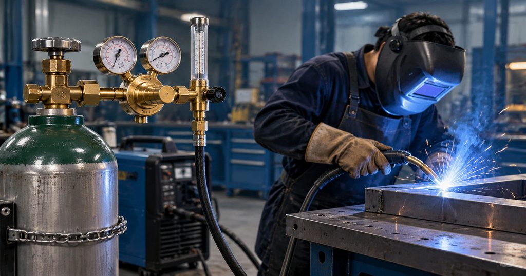
Gas flow drops during MIG welding when the shielding-gas system cannot maintain delivery under working conditions. Common causes include restricted hoses, leaks, blocked torch components, regulator cooling, insufficient supply capacity, and faulty solenoid valves. Sometimes, however, the apparent drop is simply an initial gas surge settling into normal flow.
From a gas-control manufacturer’s perspective, the most useful distinction is between pressure at the regulator and flow reaching the torch. A normal gauge reading does not guarantee adequate shielding at the weld.
Is the Gas Flow Really Dropping?
Before replacing a regulator, establish what actually changes when welding begins.
Pressure and Flow Are Different Measurements
Pressure describes the force driving gas through the system. Flow describes the volume moving through it, usually expressed in cubic feet per hour (CFH) or liters per minute (L/min).
A pressure gauge can show normal pressure upstream of a restriction while little gas reaches the nozzle. Conversely, outlet pressure may fall somewhat when gas starts moving without indicating a defective regulator.
A gauge marked in flow units may also infer flow from pressure through a calibrated restriction. It does not necessarily measure actual nozzle delivery.
An Initial Surge Can Look Like a Flow Drop
When the torch valve closes, gas can remain pressurized in the supply hose. Opening the valve releases this stored gas, producing a brief surge before steady flow develops.
If the indicated flow falls once and then remains stable, you may be observing this transition rather than progressive gas starvation.
Continued decline, repeated fluctuation, or reduced nozzle delivery during longer welds deserves further investigation.
Seven Reasons Gas Flow Drops During MIG Welding
1. The Gas Supply Cannot Sustain Demand
A nearly depleted compressed-gas cylinder may eventually lack enough inlet pressure to support the regulator’s required delivery.
However, falling cylinder pressure does not always cause a gradual decrease in outlet pressure. Some single-stage regulator designs exhibit supply pressure effect: outlet pressure rises as inlet pressure falls.
Only when the supply becomes insufficient does delivery become unsustainable.
Pure CO₂ requires additional consideration because it is commonly supplied as a liquefied gas. Cylinder cooling and available vaporization capacity can affect sustained withdrawal. Cylinder pressure alone is not a reliable inventory measure while liquid remains; use the supplier’s weighing procedure.
2. CO₂ Cooling Restricts the Regulator
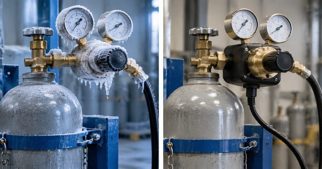
CO₂ expansion through a regulator can cause substantial cooling. Under demanding conditions, solid CO₂ formation inside the regulator can restrict passages and reduce delivery.
Typical clues include:
– Flow starts normally but declines during sustained welding.
– Frost develops around the regulator.
– Delivery improves after equipment returns to normal temperature.
– The problem becomes more pronounced in colder conditions.
External frost alone does not prove that internal passages are blocked. Compare the temperature change with actual flow behavior.
A purpose-designed CO₂ heated regulator may be appropriate when sustained withdrawal creates a verified thermal limitation. Never use a flame, boiling water, or an improvised heater to restore flow.
3. Leaks Divert Gas Before It Reaches the Torch
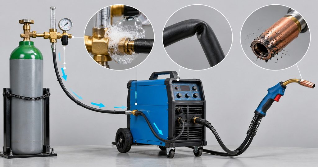
Leaks can occur at cylinder connections, regulator outlets, hose fittings, machine connections, or torch seals.
A leak downstream of a flowmeter can allow the meter to indicate gas delivery while part of that gas escapes before reaching the nozzle.
Possible warning signs include unexplained consumption, hissing, damaged hoses, and inconsistent shielding.
Use an approved leak-detection solution compatible with the equipment. Never test for leaks with a flame. Close the cylinder and follow the manufacturer’s depressurization instructions before correcting a connection.
4. Hoses and Torch Components Restrict Delivery
The regulator is only one part of the gas path. Restrictions elsewhere can reduce shielding-gas flow even when the supply is adequate.
Check for:
– Kinked or crushed gas hoses.
– Excessively tight gun-cable bends.
– Damaged fittings or incompatible connectors.
– Spatter obstructing the nozzle or diffuser.
– Incorrectly installed torch consumables.
Restrictions that change when the gun cable moves are particularly revealing. If flow falls only in certain torch positions, inspect the cable assembly before blaming the regulator.
5. The Regulator Is Undersized or Unstable Under Load
A regulator must maintain suitable outlet conditions at the required flow—not merely display an acceptable pressure while the torch is closed.
Pressure reduction as demand increases is called droop. Some droop is normal, but excessive droop can leave insufficient pressure to drive gas through downstream restrictions.
When comparing regulators, examine:
– Rated flow under stated inlet and outlet conditions.
– Available flow curves.
– Gas compatibility.
– Required delivery-pressure range.
– Performance at reduced inlet pressure.
A high maximum pressure rating does not automatically mean adequate usable flow.
6. The Solenoid Valve Does Not Open Correctly
The welder’s gas solenoid controls delivery to the torch. Contamination, mechanical sticking, electrical faults, or control problems can produce delayed, intermittent, or absent flow.
Suspect this area when the external supply appears stable but torch delivery cuts in and out with machine operation.
Use the machine’s approved gas-test function where available. Internal electrical inspection and valve servicing should be performed by qualified personnel, not attempted by bypassing safety controls.
7. The Flow Reading Is Misleading
Flowmeters must match their intended gas and operating conditions.
A variable-area flowmeter calibrated for argon may not accurately indicate pure CO₂ flow unless the manufacturer provides an appropriate scale or correction. Tube orientation and specified operating pressure also matter.
Read the float at the manufacturer’s designated reference point. Do not assume every meter uses the same reading method.
Always distinguish between indicated supply flow and measured delivery at the torch.
How Much Shielding Gas Does MIG Welding Need?
There is no universal flow setting for every MIG application.
Lincoln Electric gives approximately 30–40 CFH as typical guidance in its MIG troubleshooting material, while noting that requirements vary with wire size, amperage, transfer mode, and wind conditions. That range is approximately 14–19 L/min.
Use the applicable welding procedure, wire guidance, and equipment instructions rather than treating this range as a fixed rule.
| Operating factor | Why it matters |
|---|---|
| Nozzle geometry | Changes how gas covers the weld area |
| Shielding-gas composition | Affects process suitability and meter calibration |
| Torch angle and stand-off | Influence shielding coverage |
| Drafts | Can displace the protective gas envelope |
| Gas-path restrictions | Can reduce delivery at the nozzle |
| Welding duration | Exposes sustained supply and cooling limitations |
More gas is not automatically better. Excessive velocity can create turbulence and entrain surrounding air.
If shielding remains poor at the specified setting, investigate drafts, torch condition, leaks, and actual nozzle flow before increasing delivery.
A Practical MIG Gas-Flow Troubleshooting Procedure
Step 1: Make the Inspection Safe
Secure cylinders upright and maintain adequate ventilation. Shielding gases can displace oxygen.
For flow checks, use the approved gas-purge or gas-test function. If the equipment requires another method, follow its instructions to prevent unintended wire feeding or exposure to an energized wire.
Stop using equipment with damaged connections, persistent leakage, or suspected internal regulator faults.
Step 2: Establish a Flowing Baseline
Record the gas type, cylinder condition, regulator setting, ambient conditions, and flow indication while gas is actually moving.
A setting observed only with the torch closed does not establish operating flow.
Confirm that the flowmeter is appropriate for the gas and installed as specified.
Step 3: Compare Supply Indication With Nozzle Delivery
Use a suitable torch-end flow checker according to its instructions.
A substantial difference between indicated supply flow and nozzle delivery suggests leakage, restriction, or a measurement mismatch. Account for the accuracy and operating requirements of both instruments.
This comparison is often more useful than repeatedly adjusting the regulator.
Step 4: Inspect the Entire Delivery Path
Check the hose route, connectors, torch seals, diffuser, and nozzle.
Clean or replace consumables using the torch manufacturer’s procedure. Do not enlarge gas passages or modify calibrated restrictions.
Perform approved leak checks after reassembly.
Step 5: Reproduce the Actual Operating Pattern
A short purge may miss a problem that appears only during sustained welding.
Within the equipment’s permitted operation, compare initial delivery with delivery after a representative production sequence. Record whether flow changes with temperature, cable position, or simultaneous demand from other equipment.
Change one variable at a time so the result remains meaningful.
Step 6: Escalate With Useful Evidence
If the fault persists, provide the equipment supplier with your recorded readings, gas specification, regulator model, hose arrangement, and timing of the problem.
This information helps distinguish a supply limitation from a regulator, torch, or machine fault without unnecessary component replacement.
Diagnose the Problem by Its Timing
The timing of a gas-flow change can help narrow the investigation.
| Observed pattern | Investigate first |
|---|---|
| Brief high flow, then stable delivery | Stored-gas surge and normal settling |
| Gradual decline during sustained CO₂ use | Cooling, withdrawal capacity, regulator sizing |
| Change when the cable moves | Hose or gun-cable restrictions |
| Normal supply indication, low nozzle delivery | Leaks, restrictions, meter mismatch |
| Intermittent flow linked to machine operation | Solenoid and control function |
| Normal nozzle flow but poor shielding | Drafts, torch position, contamination |
These patterns are diagnostic clues, not proof. For example, porosity can also result from contaminated material or consumables. A defective weld alone does not establish that gas flow dropped.
Heated or Dual-Stage: Which Regulator Solves the Problem?
Choose Heated CO₂ Regulation for a Thermal Limitation
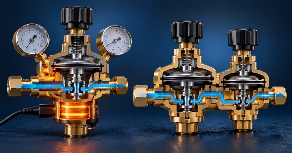
A heated regulator addresses cooling associated with CO₂ pressure reduction and withdrawal.
Selection should consider gas compatibility, continuous-flow capability, ambient conditions, electrical supply, and manufacturer installation requirements.
Heating does not repair leaks, clear a blocked diffuser, or correct an undersized cylinder arrangement.
Choose Dual-Stage Regulation for Inlet-Pressure Stability
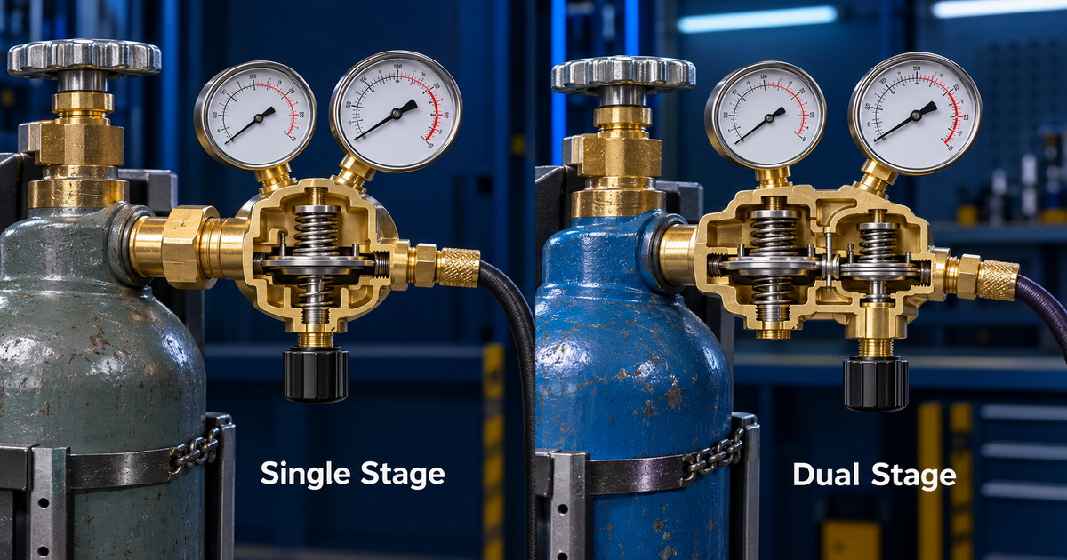
A dual-stage regulator reduces pressure in two steps. This can minimize outlet-pressure changes caused by changing cylinder pressure.
It is useful where consistent delivery pressure matters throughout cylinder use. However, dual-stage construction alone does not guarantee protection against CO₂ freezing.
A heated regulator and a dual-stage regulator address different problems, although a product may combine both features.
Also, two gauges do not mean two stages. Many single-stage regulators have separate cylinder-pressure and delivery gauges.
What Overseas Buyers Should Specify Before Ordering Regulators
From a manufacturing perspective, dependable performance begins with a complete application specification—not simply a request for a brass body and a particular gauge range.
For OEM and ODM projects, provide:
– Gas composition and cylinder connection standard.
– Required operating flow and delivery pressure.
– Minimum and maximum inlet conditions.
– Ambient-temperature range and welding duty pattern.
– Hose configuration and machine-interface requirements.
– Heater voltage, where applicable.
– Destination-market compliance and documentation requirements.
Ask suppliers how they verify leakage, delivery stability, flow indication, and sustained-load performance.
High-quality brass supports a robust regulator body, but material selection alone cannot establish overall performance. Seat design, diaphragms, seals, machining, assembly cleanliness, and testing also matter.
Do not treat oxygen, acetylene, propane, nitrogen, argon, and CO₂ regulators as interchangeable. Each application requires appropriate materials, connections, ratings, and service suitability.
Discuss Your MIG Gas-Control Requirements
If gas flow drops during MIG welding, identify where delivery changes before selecting replacement equipment.
For overseas brands, wholesalers, distributors, and equipment manufacturers, we provide OEM and ODM gas-regulator solutions, including CO₂ heated regulators, argon regulators, and dual-stage configurations.
Send us your gas specification, target flow, connection standard, operating temperature, and welding duty requirements. We can review the application and discuss a suitable configuration, customization scope, and verification requirements.
Frequently Asked Questions
1.Why does gas flow drop when I pull the MIG trigger?
A brief reduction may be an initial surge settling into steady delivery. Continued decline can indicate insufficient supply, restrictions, cooling, leakage, or regulator performance problems. Check flow while gas is moving.
2.Why does my CO₂ regulator freeze during welding?
CO₂ pressure reduction can cause substantial cooling. Under demanding conditions, internal solid formation can restrict delivery. Check sustained-flow requirements and consult the supplier about a purpose-designed heated regulator.
3.Can my regulator show pressure when no gas reaches the torch?
Yes. Pressure may remain upstream of a blocked hose, closed valve, or restricted component. Pressure indication alone does not confirm nozzle flow.
4.Will a dual-stage regulator prevent every gas-flow problem?
No. It helps minimize supply pressure effect but does not correct leaks, blocked consumables, solenoid faults, or every thermal limitation.
5.Should I increase gas flow when porosity appears?
Not automatically. Confirm nozzle delivery, inspect for drafts and leaks, and check material cleanliness. Excessive flow can disturb shielding rather than improve it.
6.Can I use an argon flowmeter for CO₂?
Only if its manufacturer specifies suitability and provides the correct scale or correction. Different gases can produce different readings on the same meter.
References
The technical explanations and diagnostic recommendations above draw on the following manufacturer and engineering resources. The troubleshooting sequence and buyer checklist are an editorial synthesis, not a report of a controlled product test.
1. Lincoln Electric — “MIG Problems and Remedies.” Guidance on shielding-gas flow, operating variables, and MIG welding defects. [lincolnelectric]
2. Harris Products Group — “Carbon Dioxide Regulator Freezing.” Explanation of CO₂ regulator cooling, solid formation, and heated-regulator design. [harrisproductsgroup]
3. Swagelok, Wouter Pronk, Senior Field Engineer — “How to Manage Supply Pressure Effect in Pressure-Reducing Regulators.” Explains inlet dependency, regulator design, and two-stage pressure reduction. [swagelok]
4. SMC Automation / AP Tech — “Droop, SPE and Pressure Setting.” Technical training covering static and dynamic settings, droop, and supply pressure effect. [smcautomation]
5. Harris Products Group — “Gas Regulation.” Selection guidance for applications requiring more consistent delivery pressure. [harrisproductsgroup]
6. NetWelding — “MIG Shielding Gas Control and Optimization.” Technical discussion of start-up surges, gas-path restrictions, and excessive-flow turbulence. [netwelding]
Hot Tags: MIG Welding Gas Regulator, CO₂ Gas Regulator, CO₂ Heated Regulator, Argon Gas Regulator, Dual Stage Gas Regulator, Welding Gas Flow Meter, Industrial Gas Regulator, Gas Regulator Manufacturer, OEM Gas Regulator, MIG Welding Gas Flow Problems