Content Menu
● What Is the Difference Between a Flowmeter and a Pressure Gauge?
>> Pressure Gauge: What It Tells You
>> Flowmeter: What It Tells You
● Flowmeter vs Pressure Gauge Comparison for Welding Gas
● Why Actual Flow Matters for Shielding Gas Optimization
>> The Risk of Setting Gas by Pressure Alone
>> Why Excessive Gas Flow Can Reduce Weld Quality
● When to Choose a Flowmeter Regulator
● When a Pressure Gauge Regulator Is the Better Choice
● Flowmeter vs Pressure Gauge: A Practical Selection Framework
>> Choose Based on the Controlled Variable
>> Consider Cylinder Pressure Stability
● Expert Setup Method for Shielding Gas Flow
>> Step-by-Step Setup Checklist
● A Production Example: Avoiding Hidden Gas Waste
● OEM and ODM Considerations for Gas Regulator Buyers
● Improve Gas Control With the Right Regulator
● FAQ
>> 1. Is a flowmeter better than a pressure gauge for MIG welding?
>> 2. Can I use a pressure gauge regulator for argon or CO₂ welding?
>> 3. Does higher shielding gas flow always prevent porosity?
>> 4. What is the difference between a single-stage and dual-stage gas regulator?
>> 5. Can one regulator be used for every industrial gas?
>> 6. Why is a CO₂ heated regulator used?
>> 7. How should I set a shielding gas flowmeter?
Choosing between a flowmeter vs pressure gauge is one of the most important decisions for controlling shielding gas in MIG, TIG, robotic welding, and other industrial gas applications. Both devices work with a gas regulator, but they measure different variables—and confusing pressure with actual gas flow can lead to porosity, unstable weld appearance, unnecessary gas consumption, and inconsistent production costs.
For most welding operations, a flowmeter-equipped CO₂ or argon regulator provides the more direct way to optimize shielding gas delivery because it displays gas volume per unit of time, typically in L/min or CFH. A pressure gauge remains essential for monitoring cylinder pressure and regulated outlet pressure, but pressure alone does not reliably show how much shielding gas reaches the torch. ISO 2503 covers regulators both with and without flow-metering devices for welding, cutting, and allied processes, including CO₂ and compressed-gas mixtures.
What Is the Difference Between a Flowmeter and a Pressure Gauge?
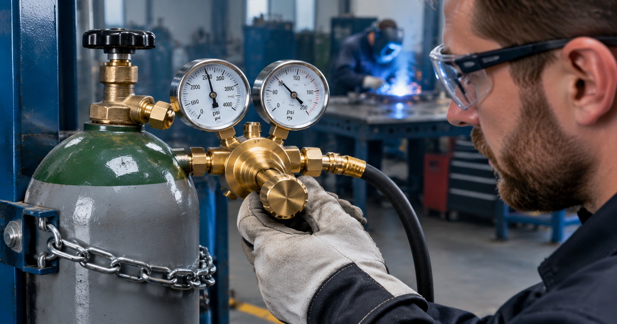
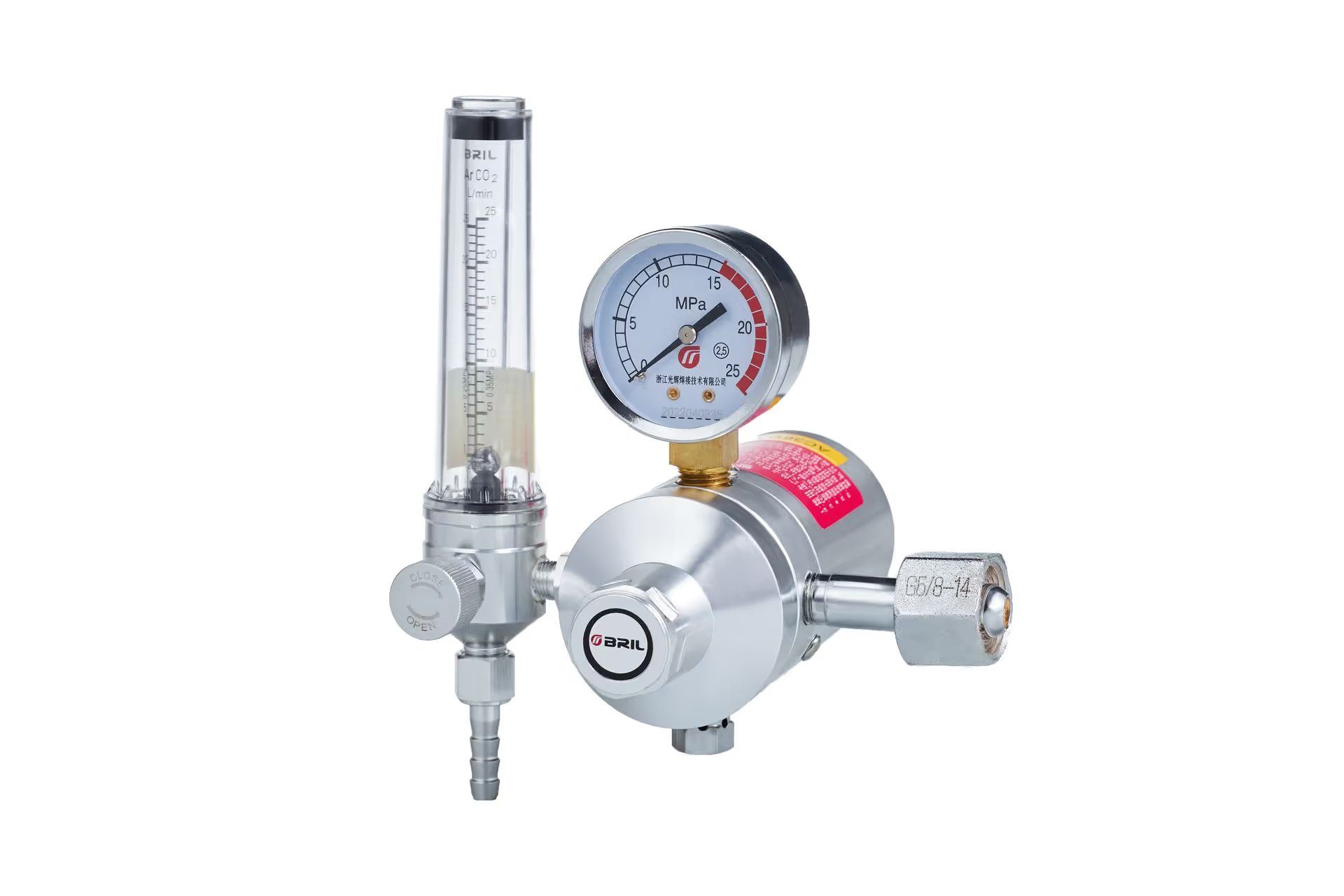
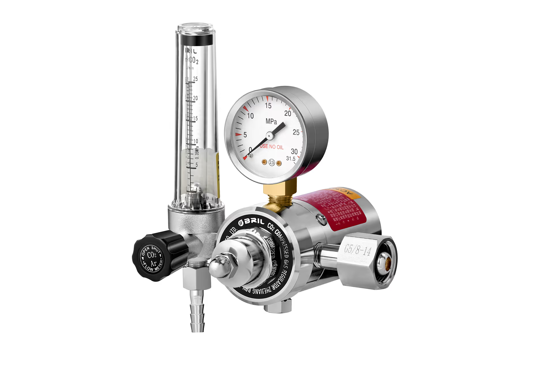
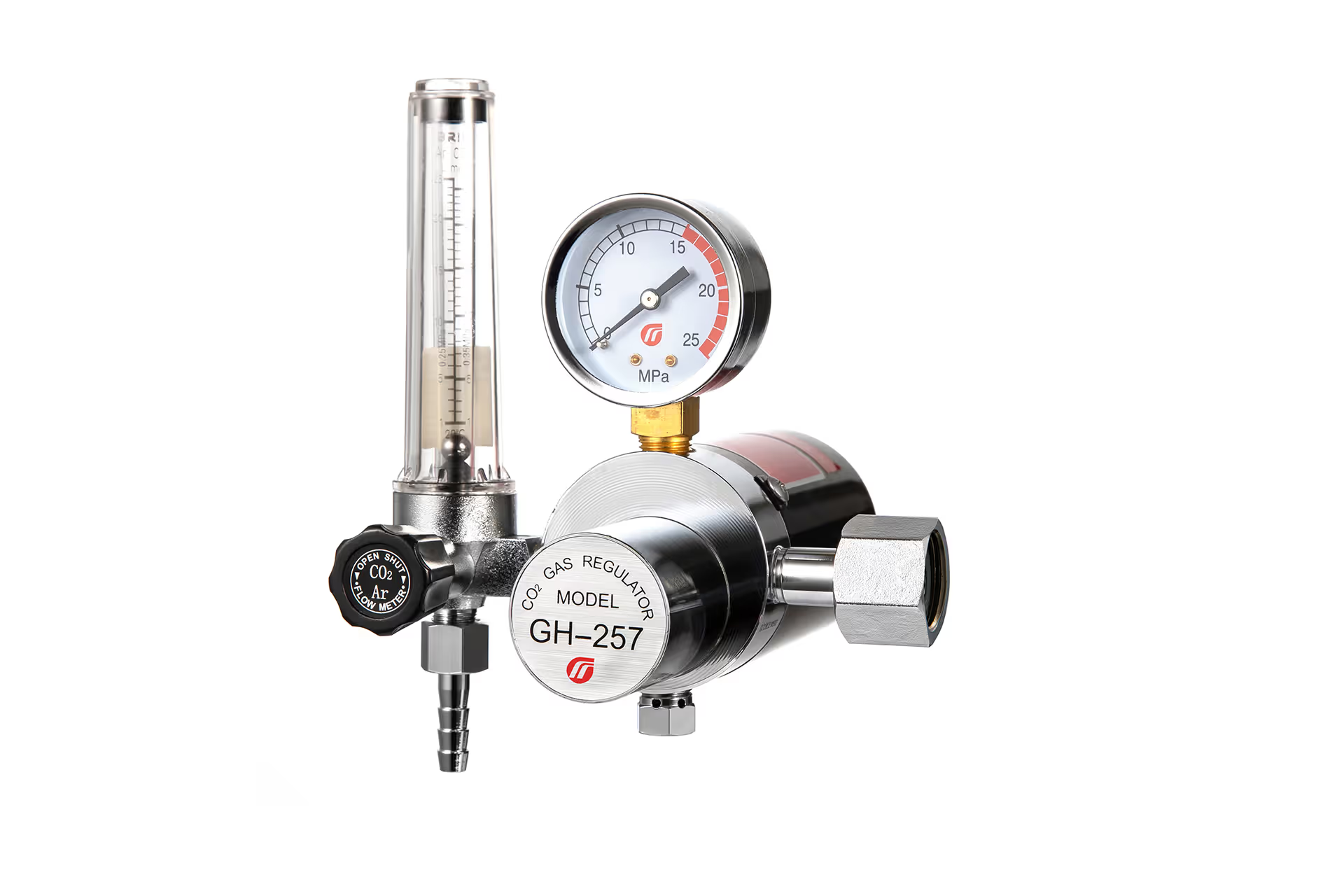
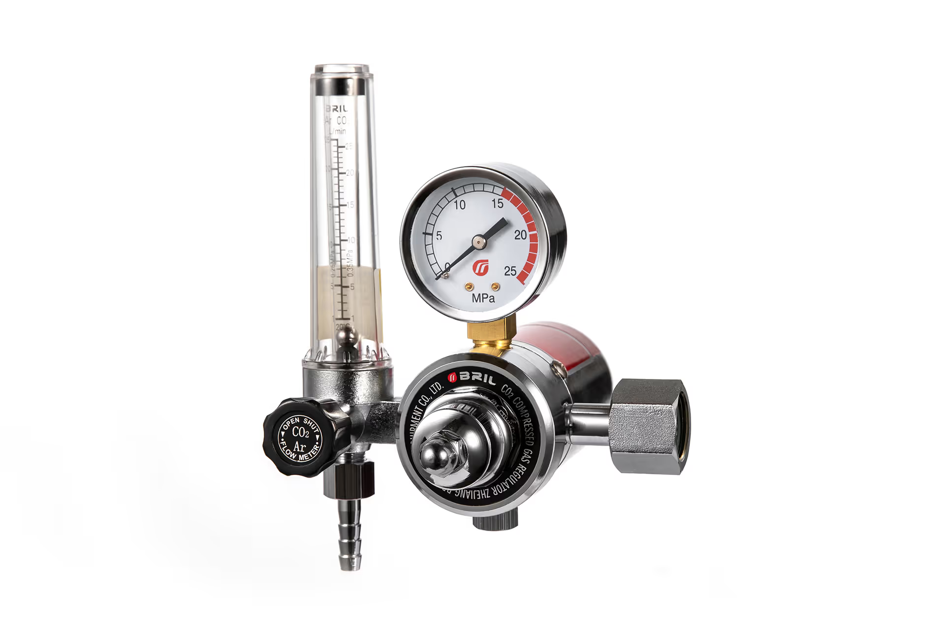
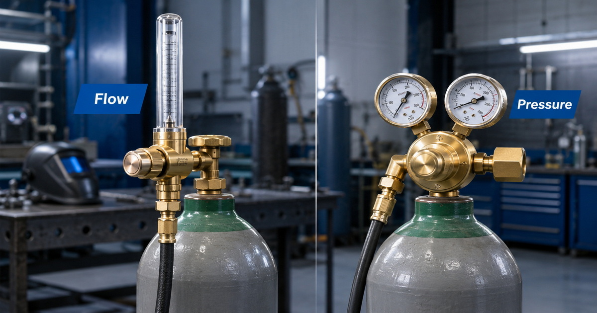
A pressure gauge measures the force exerted by gas within a closed system. It is usually displayed in psi, bar, or MPa. On a standard dual-gauge gas regulator, one gauge commonly indicates cylinder pressure, while the other shows regulated outlet pressure.
A flowmeter measures the volume of gas moving through the system over time. For shielding gas, it is commonly calibrated in:
– Liters per minute (L/min) in many international markets
– Cubic feet per hour (CFH) in the United States
– Occasionally liters per hour or other project-specific units
This distinction matters because a welding torch needs a stable gas *flow rate*, not merely a specific pressure reading. Flow creates the protective gas envelope around the molten weld pool. Pressure is only one factor that contributes to that final flow.
Pressure Gauge: What It Tells You
A pressure gauge is valuable for two primary reasons:
– It helps the operator see cylinder pressure or approximate remaining gas availability.
– It indicates the regulator’s outlet or working pressure.
For oxygen, acetylene, propane, nitrogen, compressed air, and many cutting applications, outlet-pressure control is often central to safe and stable equipment operation. Pressure gauge regulators are therefore common across gas welding, cutting, heating, laboratory, and industrial distribution systems.
However, a pressure gauge does not directly measure shielding gas volume at the torch. If hose length, hose diameter, leaks, fittings, torch design, solenoid behavior, restrictions, or contact-tip conditions change, the same outlet pressure can produce a different actual flow result.
Flowmeter: What It Tells You
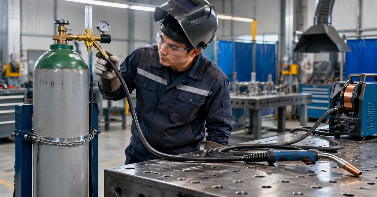
A flowmeter regulator combines pressure reduction with a mechanism that indicates gas flow. A common design uses a vertical transparent rotameter tube, where a ball rises with gas flow. Operators read the ball position against a graduated scale in L/min or CFH.
This design gives welders a direct setting for shielding gas delivery. Instead of asking, “What outlet pressure should I use?” the operator can set the documented flow requirement for the weld procedure.
A flowmeter regulator typically reduces high cylinder pressure first, then allows the operator to adjust and read gas volume on the delivery side.
Flowmeter vs Pressure Gauge Comparison for Welding Gas
| Comparison factor | Flowmeter regulator | Pressure gauge regulator |
|---|---|---|
| Primary measurement | Gas volume over time | Gas pressure |
| Typical units | L/min or CFH | psi, bar, MPa |
| Best use | Shielding gas optimization | Working-pressure control |
| Directly indicates torch gas flow | Yes, subject to setup conditions | No |
| Suitable for MIG and TIG | Highly suitable | Usable, but less direct for flow setup |
| Cylinder content monitoring | Often includes a cylinder-pressure gauge | Usually included as one gauge |
| Operator adjustment | Set to a target flow | Set pressure, then infer flow |
| Repeatability across welding stations | Generally stronger | Can vary with system conditions |
| Gas-saving potential | Better visibility of over-flow | Harder to identify excessive flow |
| Typical gases | Argon, CO₂, argon/CO₂ mixtures, helium blends | Oxygen, acetylene, propane, nitrogen, air, and shielding gases |
Why Actual Flow Matters for Shielding Gas Optimization
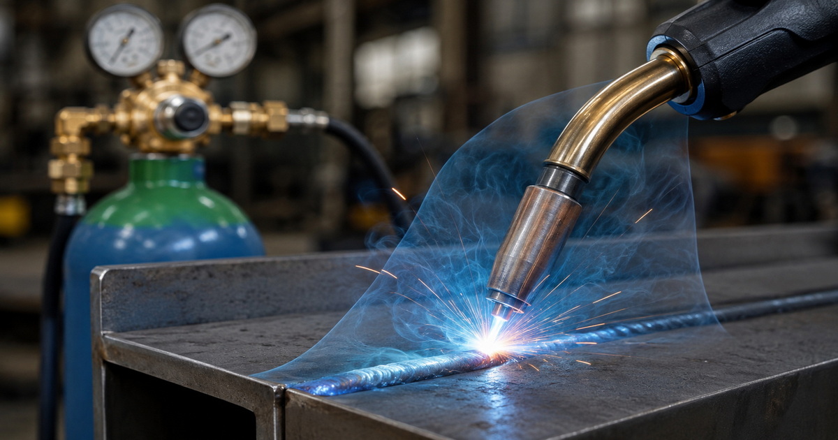
Shielding gas protects the weld pool from atmospheric contamination. If the flow is too low, air can enter the weld zone and increase the risk of porosity, oxidation, discoloration, and inconsistent bead quality. If flow is too high, the operation may waste gas and create turbulence that pulls surrounding air into the shielding envelope.
This is why “more gas” is not automatically better gas protection.
The Risk of Setting Gas by Pressure Alone
A pressure gauge regulator can work for shielding gas, particularly where welding teams have established and validated a machine-specific pressure setting. But the method depends on assumptions that may no longer hold after changes in the gas delivery system.
For example, a pressure setting that performs well on one MIG machine may not transfer perfectly to another station with:
– A longer or narrower gas hose
– A partially restricted diffuser or gas liner
– A different torch length or neck geometry
– A leaking quick connector
– A different wire feeder or solenoid valve
– A changed gas mixture
– A different nozzle size
A pressure-gauge setting is therefore an indirect control method. It can be practical, but it needs validation.
Why Excessive Gas Flow Can Reduce Weld Quality
Many operators increase gas flow after seeing porosity. Yet if the root cause is drafts, contamination, a leaking hose, a blocked gas diffuser, or incorrect torch angle, higher flow may not solve the problem.
In some conditions, excessive flow creates turbulent gas movement around the nozzle. That turbulence can disturb the protective gas coverage and draw ambient air toward the arc area. It also increases cylinder consumption without creating a proportional productivity benefit.
The right objective is stable, verified, application-appropriate flow—not the highest possible reading.
When to Choose a Flowmeter Regulator
A flowmeter regulator is usually the better choice when shielding gas consistency is a key quality or cost-control target.
Choose a flowmeter for:
– MIG/MAG welding with CO₂ or argon/CO₂ mixtures
– TIG welding with argon or argon-based mixtures
– Robotic welding cells requiring repeatable parameters
– Multi-shift fabrication where operators need standardized settings
– Contract manufacturing and OEM production
– Welding procedure qualification and documented work instructions
– Operations seeking to reduce avoidable shielding gas usage
– Distributor product lines focused on professional welding users
For a manufacturer, this creates a clear product-positioning opportunity: a brass CO₂ flowmeter regulator can be marketed as a practical tool for process consistency, operator simplicity, and gas-control visibility.
When a Pressure Gauge Regulator Is the Better Choice
A pressure gauge regulator remains the right product for many gas-control applications. It should not be treated as obsolete or inferior; it simply solves a different control problem.
A pressure gauge regulator is often appropriate for:
– Oxy-fuel cutting systems
– Oxygen and acetylene welding or brazing
– Propane heating equipment
– Nitrogen purging where a specified pressure is required
– Pneumatic or gas-powered equipment
– Applications requiring a stable downstream pressure rather than a measured flow
– Cost-sensitive welding setups with validated pressure-based procedures
For acetylene, oxygen, and other gas applications, compatibility, correct inlet connection, pressure range, and safe materials selection are critical. Regulators must not be adapted to incompatible cylinder connections. USC Environmental Health & Safety specifically warns against using adapters to connect a regulator to a cylinder with a different CGA fitting.
Flowmeter vs Pressure Gauge: A Practical Selection Framework
When advising distributors, private-label buyers, or welding-equipment brands, we recommend evaluating the end use before selecting a regulator configuration.
Choose Based on the Controlled Variable
Ask one simple question:
Does the process need a controlled pressure or a controlled gas flow rate?
If the answer is shielding gas delivery to a MIG or TIG torch, flow is normally the variable that the welder needs to set and repeat. If the answer is a cutting torch, pressure-driven system, purging system, or industrial gas line, outlet pressure may be the more relevant variable.
Consider the Gas Type
Different gases behave differently and require purpose-designed regulator configurations, seals, connection standards, and pressure ranges.
| Gas | Common application | Preferred control focus |
|---|---|---|
| CO₂ | MIG/MAG welding | Flow for shielding gas |
| Argon | TIG and MIG welding | Flow for shielding gas |
| Argon/CO₂ mix | MIG/MAG welding | Flow for shielding gas |
| Oxygen | Cutting and welding | Outlet pressure |
| Acetylene | Oxy-fuel welding and cutting | Outlet pressure |
| Propane | Heating and cutting | Outlet pressure |
| Nitrogen | Purging, testing, industrial use | Pressure or flow, depending on process |
ISO 2503 addresses single-stage and dual-stage pressure regulators, including models with flow-metering devices, used with gas cylinders in welding, cutting, and allied processes up to 300 bar for applicable gases.
Consider Cylinder Pressure Stability
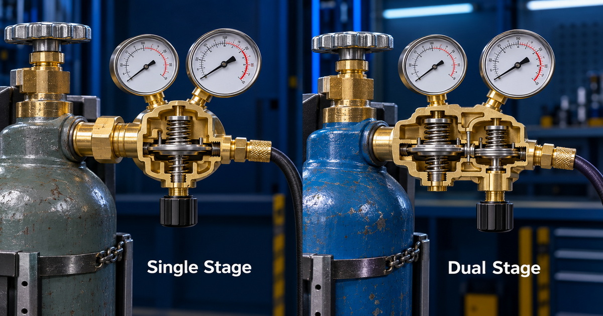
A single-stage regulator reduces cylinder pressure in one step. As cylinder pressure decreases, outlet conditions can gradually change, depending on regulator design and demand.
A dual-stage gas regulator reduces pressure in two stages. It is often selected where greater outlet-pressure stability is needed as the cylinder empties. This can be particularly valuable for industrial operations where process interruption, rework, and parameter drift are costly.
For high-demand or sensitive applications, the strongest configuration may be a dual-stage regulator paired with downstream flow measurement.
Expert Setup Method for Shielding Gas Flow
In our experience with industrial gas-control products, the correct regulator is only part of the result. Installation, inspection, and verification determine whether the system delivers stable gas protection.
Step-by-Step Setup Checklist
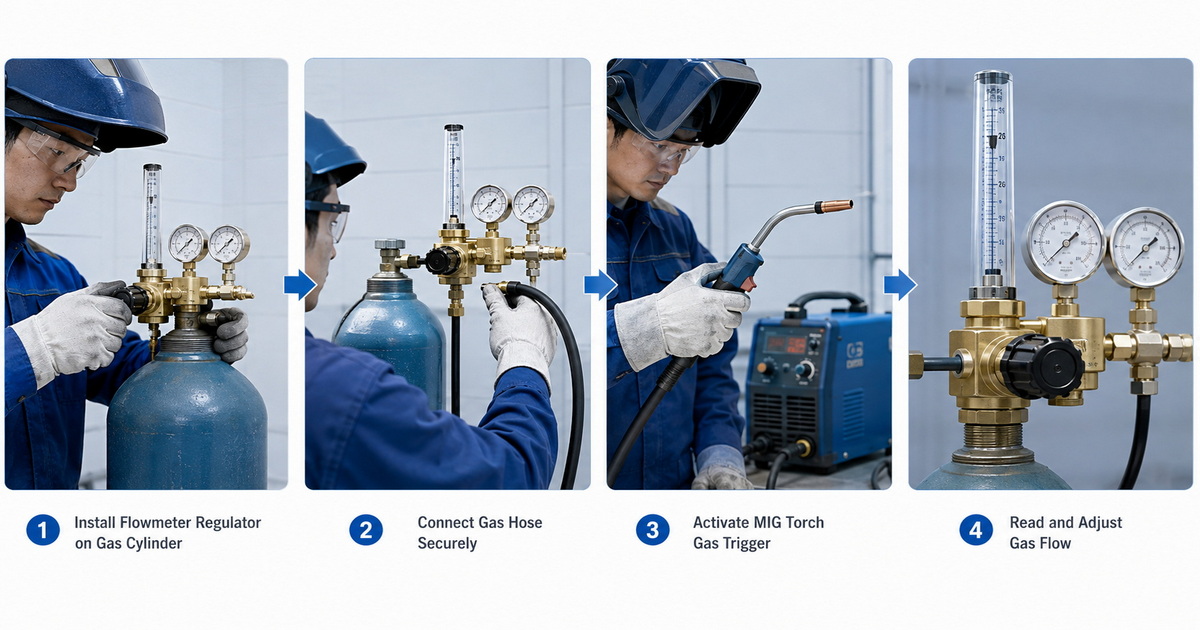
1. Confirm the regulator is designed for the gas type, cylinder valve connection, inlet pressure, and expected outlet range.
2. Inspect the regulator, hose, fittings, seals, torch connection, and flowmeter for visible damage or contamination.
3. Ensure the adjustment valve is backed out or closed as required by the product instructions before opening the cylinder valve.
4. Open the cylinder valve gradually and stand away from the regulator face.
5. Check all connections for leaks using an approved leak-detection method.
6. Trigger gas flow through the welding torch before setting the flowmeter. This matters because a static reading may not reflect real operating flow.
7. Adjust to the flow specified by the welding procedure specification (WPS), equipment manufacturer, or validated production trial.
8. Recheck flow after changing hoses, torches, gas diffusers, nozzle sizes, gas mixtures, or production-cell layouts.
9. Record the validated setting in the workstation instruction sheet.
A Production Example: Avoiding Hidden Gas Waste
Consider a fabrication workshop using CO₂/argon mixed gas for MIG welding. Operators set conventional pressure-gauge regulators to the same nominal outlet pressure at each station. The company assumes every torch receives similar shielding gas flow.
In practice, one station has a longer gas hose and another has a partially obstructed diffuser. The operator at the restricted station increases regulator pressure to compensate. A third operator, seeing occasional porosity caused by a nearby draft, also increases pressure.
The result is inconsistent gas delivery, no shared flow baseline, and higher gas consumption. By moving to flowmeter regulators and setting each station to a validated flow target while gas is actively flowing, the workshop can standardize operator setup. The team can then investigate leaks, drafts, torch condition, and consumable maintenance separately rather than attempting to solve every problem with extra gas.
The key lesson is simple: measure the process variable you actually want to control.
OEM and ODM Considerations for Gas Regulator Buyers
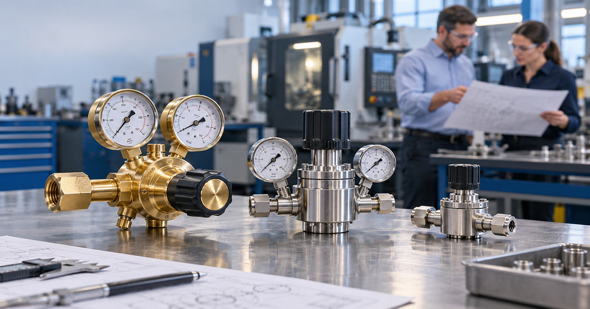
For overseas brands, wholesalers, and industrial-equipment manufacturers, selecting a gas regulator supplier involves more than choosing a gauge style.
A dependable OEM or ODM gas regulator project should define:
– Gas type and intended application
– Inlet connection standard and market destination
– Outlet connection and hose specification
– Single-stage or dual-stage design
– Pressure range or flow range
– Gauge scale in psi, bar, MPa, L/min, or CFH
– Brass grade and internal-component requirements
– Safety devices, relief design, and sealing materials
– Branding, packaging, manuals, and private-label requirements
– Inspection standards, leak testing, and batch traceability
For shielding gas, a flowmeter regulator can support a stronger value proposition because it gives users a visible, understandable gas-flow setting. For cutting, heating, oxygen, acetylene, propane, and nitrogen systems, a pressure gauge regulator may better match process requirements.
Improve Gas Control With the Right Regulator
The flowmeter vs pressure gauge decision should be based on what the process needs to control. For MIG and TIG shielding gas, a flowmeter regulator gives the operator a direct way to set and repeat gas delivery in L/min or CFH. For pressure-dependent processes such as cutting, heating, purging, and many industrial gas applications, a pressure gauge regulator remains essential.
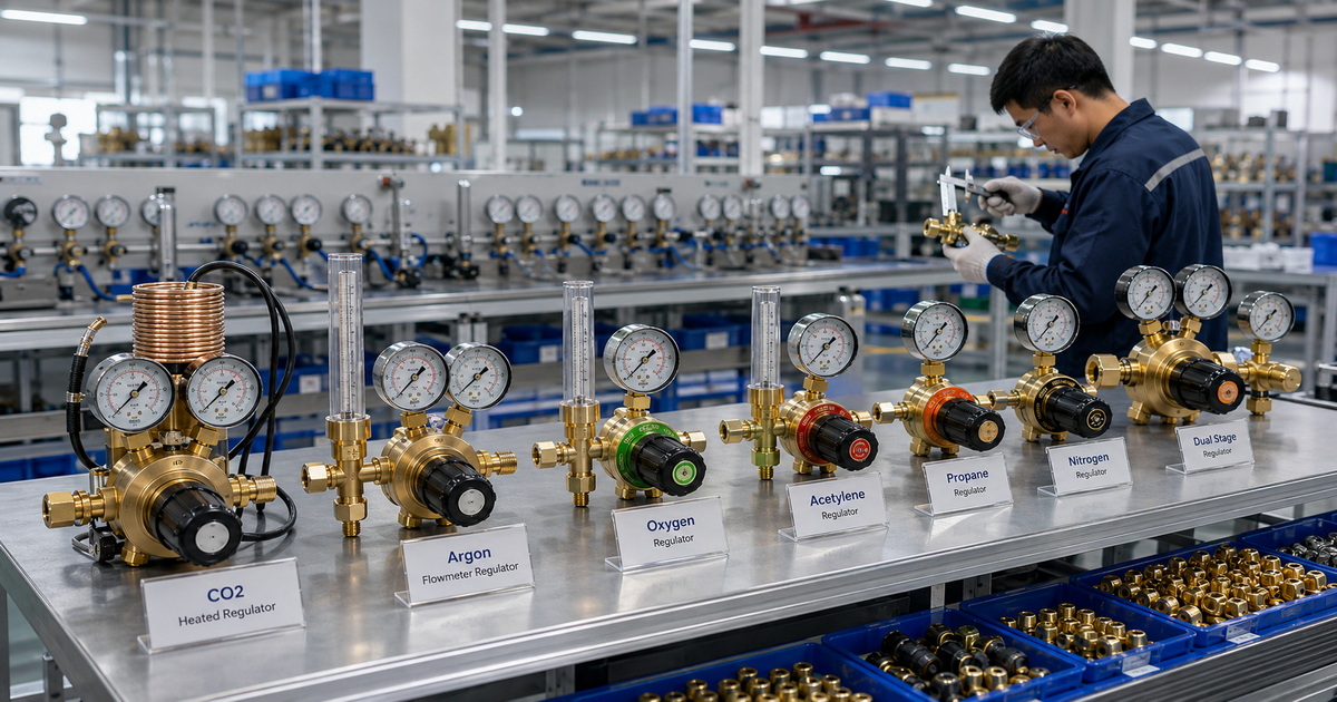
A well-designed regulator should combine accurate control, durable brass construction, gas-specific compatibility, stable performance, and thorough quality inspection. Whether you need CO₂ heated regulators, argon flowmeter regulators, oxygen and acetylene regulators, propane regulators, nitrogen regulators, or dual-stage industrial gas regulators, the correct configuration helps improve safety, weld consistency, and operating efficiency.
Looking for an OEM or ODM gas regulator manufacturer? Contact our team to discuss your target gas, application, connection standards, pressure or flow range, branding requirements, and quality-control expectations. We can help develop customized industrial gas regulator solutions for distributors, welding brands, and equipment manufacturers.
FAQ
1. Is a flowmeter better than a pressure gauge for MIG welding?
For most MIG welding shielding gas applications, yes. A flowmeter displays gas volume in L/min or CFH, which is the variable operators usually need to set. A pressure gauge shows pressure, not direct shielding gas flow.
2. Can I use a pressure gauge regulator for argon or CO₂ welding?
Yes, provided the regulator is compatible with the gas and cylinder connection. However, the pressure setting is an indirect way to control shielding gas delivery. A flowmeter is generally easier to standardize across operators and workstations.
3. Does higher shielding gas flow always prevent porosity?
No. Excessive flow can waste gas and may create turbulence around the weld zone. Porosity may also result from leaks, drafts, contaminated base metal, poor torch angle, inadequate pre-flow, damaged consumables, or incorrect welding parameters.
4. What is the difference between a single-stage and dual-stage gas regulator?
A single-stage regulator reduces cylinder pressure in one step. A dual-stage regulator reduces pressure in two steps and is often chosen where more stable outlet pressure is needed as cylinder pressure declines.
5. Can one regulator be used for every industrial gas?
No. Regulators must be selected for the specific gas, pressure range, cylinder-valve connection, materials, and application. Never force or adapt incompatible connections.
6. Why is a CO₂ heated regulator used?
A CO₂ heated regulator is designed to help manage temperature-related performance issues that can occur when CO₂ expands and cools during higher-demand use. The exact product specification should match the operating flow, duty cycle, ambient conditions, and cylinder configuration.
7. How should I set a shielding gas flowmeter?
Open the cylinder valve according to the regulator instructions, activate gas flow through the torch, and adjust the flowmeter while gas is flowing. Use the value specified in the WPS or confirmed through a controlled production test.
References
1. International Organization for Standardization. “[ISO 2503:2009 — Gas welding equipment: Pressure regulators and pressure regulators with flow-metering devices for gas cylinders used in welding, cutting and allied processes up to 300 bar (30 MPa).]” Accessed August 18, 2026.
2. Occupational Safety and Health Administration. “[NRTL Requirements for Shielding Gas Regulators.]” April 24, 2012.
3. University of Southern California Environmental Health & Safety. “[Gas Regulators.]” Accessed August 18, 2026.
4. Zoro Tools. “[Welding Regulator Selection Guide.]” November 26, 2019.
5. BSI Knowledge. “[BS EN ISO 2503:2009+A1:2015: Gas Welding Equipment—Pressure Regulators and Pressure Regulators With Flow-Metering Devices.]” Accessed August 18, 2026.
6. GCE Group. “[Quality Standards for Industrial Products.]” Accessed August 18, 2026.
Hot Tags: Flowmeter Regulator, Pressure Gauge Regulator, Shielding Gas Regulator, CO2 Flowmeter Regulator, Argon Flowmeter Regulator, Industrial Gas Regulator, Dual Stage Gas Regulator, Welding Gas Regulator, Gas Flow Control Regulator, OEM Gas Regulator Manufacturer