Content Menu
● What Is the Difference Between a Welding Gas Flow Meter and an Argon Flow Meter?
>> Why gas-specific calibration matters
● Why Aluminum Welding Requires an Argon-Compatible Flowmeter
>> Recommended shielding-gas choices
● Welding Gas Flow Meter vs Argon Flow Meter: Detailed Comparison
>> 3. Cylinder connection and safety
>> 4. Flow range and resolution
● How to Set Argon Flow for Aluminum Welding
>> The “more gas is better” myth
● A Field-Test Method for Verifying Real Torch Flow
>> Five-step verification process
● Common Selection Mistakes for Distributors and OEM Buyers
>> Buying by appearance instead of specification
>> Using a CO₂ meter as an argon meter
>> Confusing pressure with flow
>> Ignoring regional compliance requirements
● How to Specify an OEM Argon Flowmeter Regulator
● FAQ
>> 1. Can I use a CO₂ welding regulator for argon?
>> 2. What gas flow should I use for MIG welding aluminum?
>> 3. Why does my aluminum weld have black soot or porosity?
>> 4. Is a dual-stage argon regulator worth the extra cost?
>> 5. Can I use one flowmeter for argon and argon/helium blends?
>> 6. Should I choose CFH or L/min?
>> 7. How often should an argon flowmeter regulator be inspected?
For aluminum welding, the right question is not simply whether to buy a welding gas flow meter or an argon flow meter. It is whether the complete regulator-and-flowmeter assembly is designed, calibrated, connected, and operated for the actual shielding gas—usually pure argon or an argon/helium blend.
In my experience working with industrial gas-control applications, many gas-coverage problems are misdiagnosed as welding-machine or operator issues. The real cause is often simpler: an incorrectly specified flowmeter, an unsuitable cylinder connection, leakage, or excessive flow that pulls surrounding air into the shielding envelope. For aluminum, stable and correctly measured inert-gas delivery is essential because the weld pool is highly vulnerable to contamination.
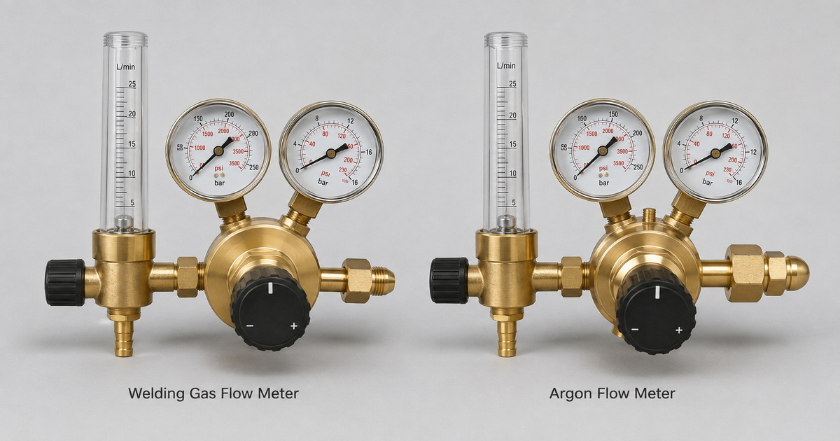
What Is the Difference Between a Welding Gas Flow Meter and an Argon Flow Meter?
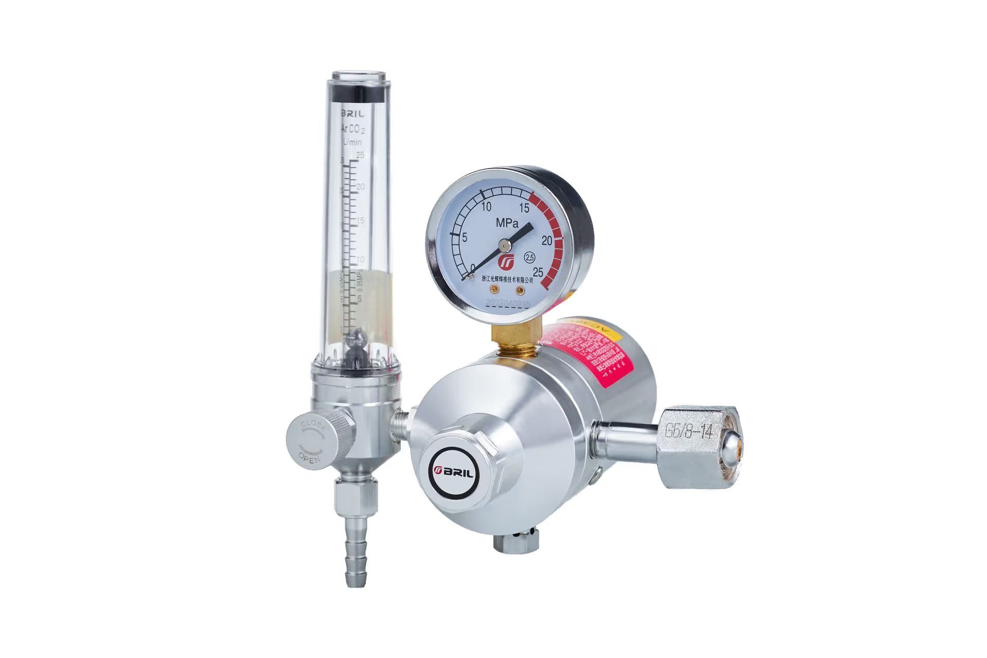
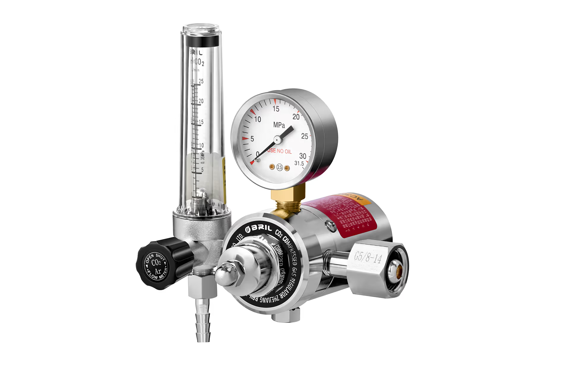
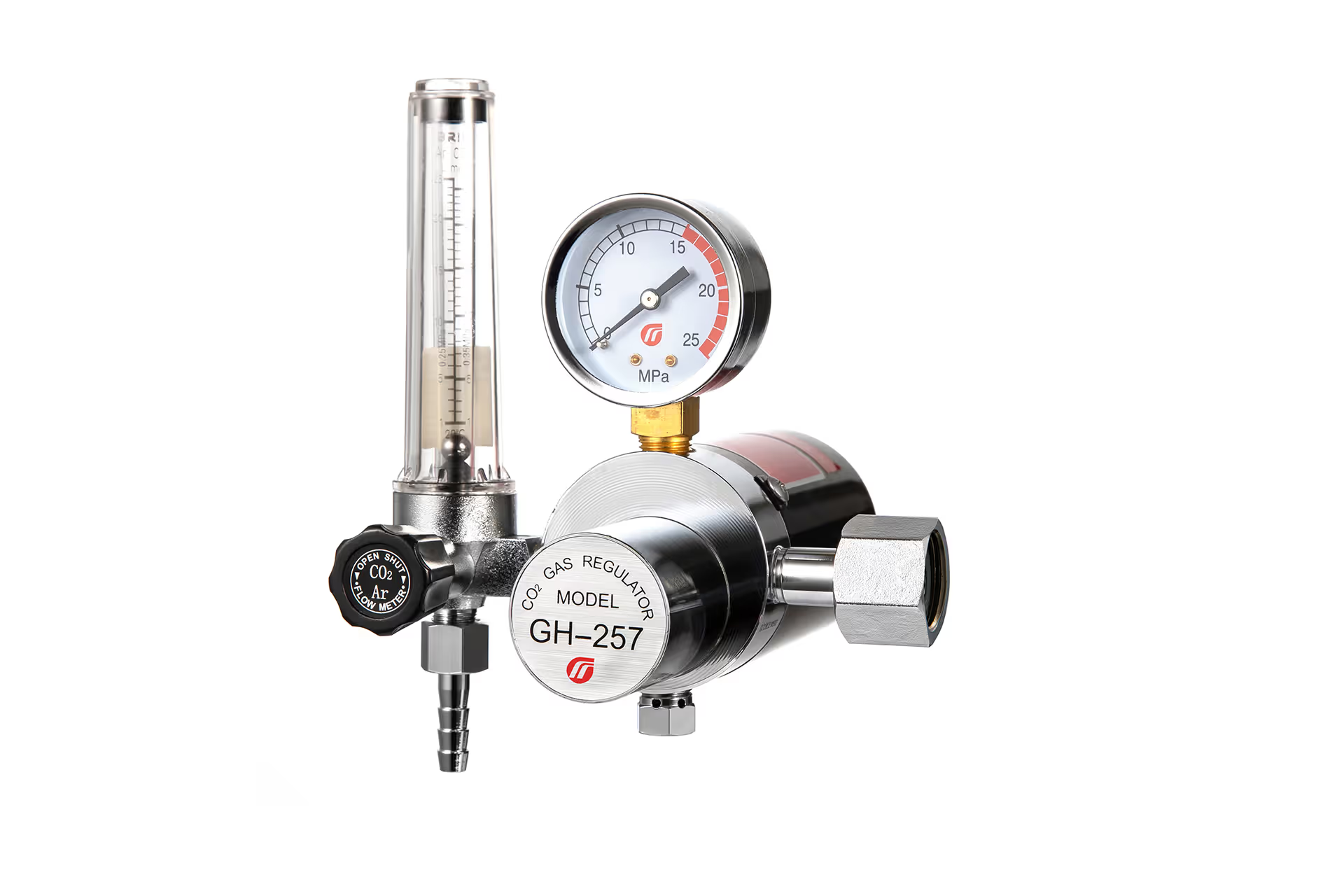
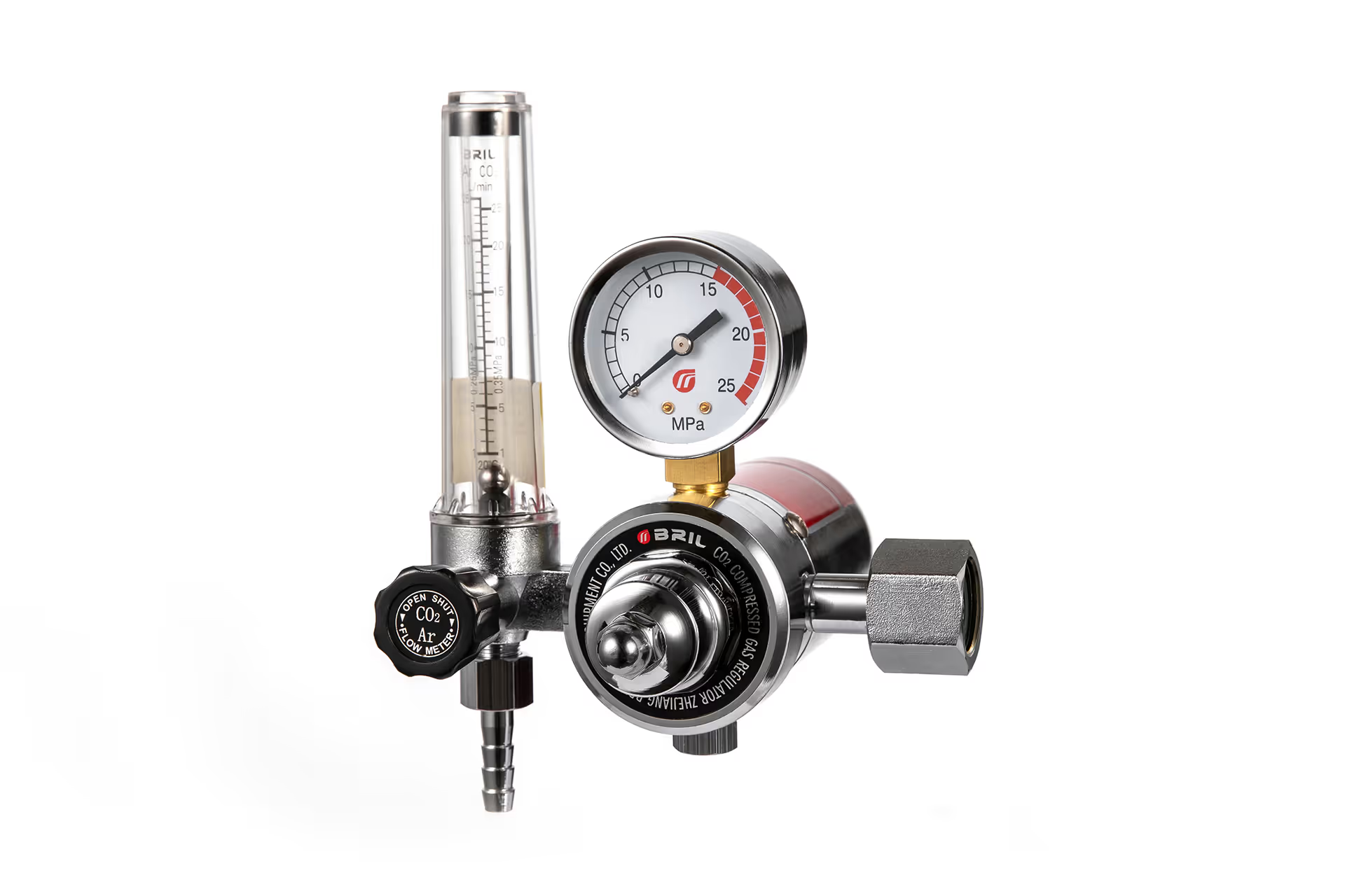
A welding gas flow meter is a broad product category. It may refer to a flowmeter regulator used for MIG, TIG, FCAW, plasma cutting, purging, or other gas-shielded processes. Depending on the model, it can be designed for argon, CO₂, argon/CO₂ mixes, oxygen, nitrogen, helium, or another gas.
An argon flow meter is a more specific product. Its flow tube, float, scale, delivery pressure, inlet connection, and published flow range are configured for argon or, where stated by the manufacturer, certain argon mixtures.
Why gas-specific calibration matters
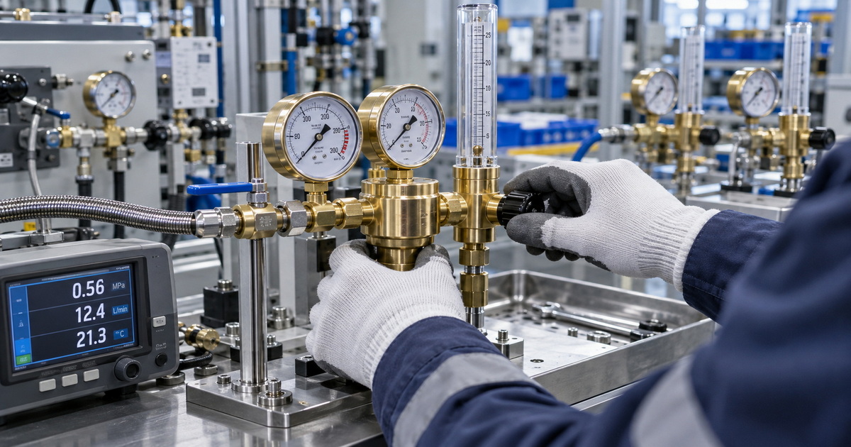
Most traditional welding flowmeters use a variable-area tube and floating ball. The ball rises according to the gas flow passing through the tube. However, gas density and viscosity influence the float position. Therefore, a flow scale intended for one gas should not automatically be treated as accurate for another gas.
The American Welding Society notes that flowmeter scales can differ by gas because gases have different densities; a standard regulator with a fixed orifice is also less accurate when used with gases outside its intended specification.
| Feature | General Welding Gas Flow Meter | Argon Flow Meter for Aluminum Welding |
|---|---|---|
| Product meaning | Broad category; suitability depends on the exact model | Purpose-specific assembly for argon service |
| Scale | May be labeled for one or multiple gases | Usually calibrated in CFH or L/min for argon |
| Cylinder inlet | Varies by regional gas standard and gas type | Must match the approved inert-gas cylinder valve |
| Typical aluminum use | Suitable only if argon-compatible | Preferred choice for TIG and MIG aluminum |
| Main risk if selected incorrectly | Wrong flow reading, fitting mismatch, poor process consistency | Lower risk when correctly specified and installed |
| Purchasing priority | Verify specifications, not product name | Verify range, connection, flow accuracy, and certification |
Why Aluminum Welding Requires an Argon-Compatible Flowmeter
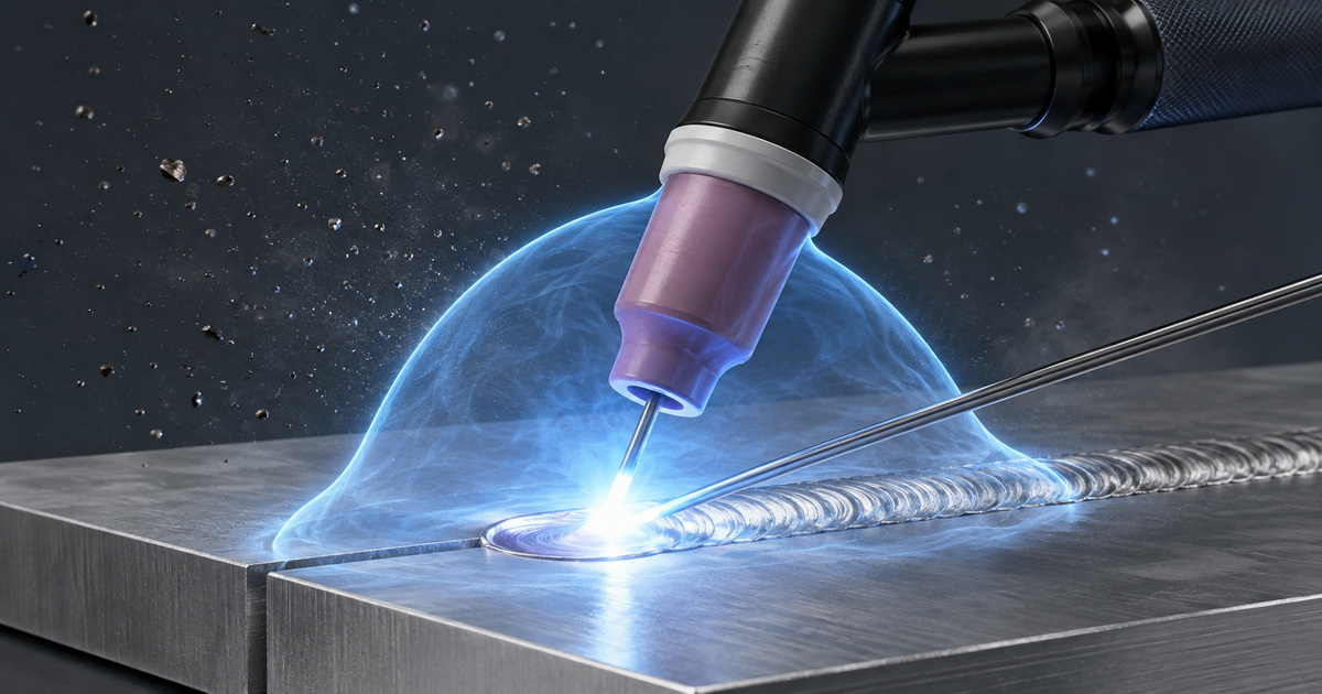
Aluminum welding normally relies on inert shielding gas. For MIG welding, 100% argon is widely used for aluminum and supports spray or pulsed-spray transfer. Miller Electric specifically recommends 100% argon for MIG aluminum and gives 20–30 CFH as a typical flow-rate range.
CO₂ is not an appropriate shielding gas for standard aluminum MIG or TIG welding. It is reactive in this context and is typically associated with carbon-steel welding applications or compatible steel filler-metal processes—not aluminum shielding. Lincoln Electric, for example, lists 100% CO₂ and 75% argon/25% CO₂ for an FCAW steel wire, while its aluminum guidance specifies 100% argon.
Recommended shielding-gas choices
– 100% argon: The normal starting point for TIG and MIG welding of aluminum.
– Argon/helium blend: A possible option for thicker aluminum, higher heat input, or applications needing greater penetration; it requires a meter and settings appropriate to the blend.
– CO₂ or argon/CO₂ mix: Generally unsuitable for aluminum welding shielding.
– Nitrogen, oxygen, propane, or acetylene regulators: Never substitute these for argon service unless the complete product specification explicitly permits the intended gas and connection system.
For TIG welding, Miller states that 100% argon is the best general-purpose shielding gas and that typical TIG flow rates range from 10 to 35 CFH, depending on consumables and environmental conditions.
Welding Gas Flow Meter vs Argon Flow Meter: Detailed Comparison
1. Flow-reading accuracy
An argon flow meter gives its best value when its scale is calibrated for argon at its stated operating conditions. This helps the welder set and repeat an actual volumetric gas-flow target rather than relying on estimated outlet pressure.
A generic flowmeter may still work perfectly well if it has a clearly marked argon scale or a multi-gas conversion scale. But a meter labeled only for CO₂, oxygen, or a different gas should not be assumed to display true argon flow.
Expert purchasing rule: Ask the supplier, “Is the scale calibrated for pure argon, and what is the rated accuracy across the working range?” Avoid accepting “universal” as a substitute for a published specification.
2. Regulator stability
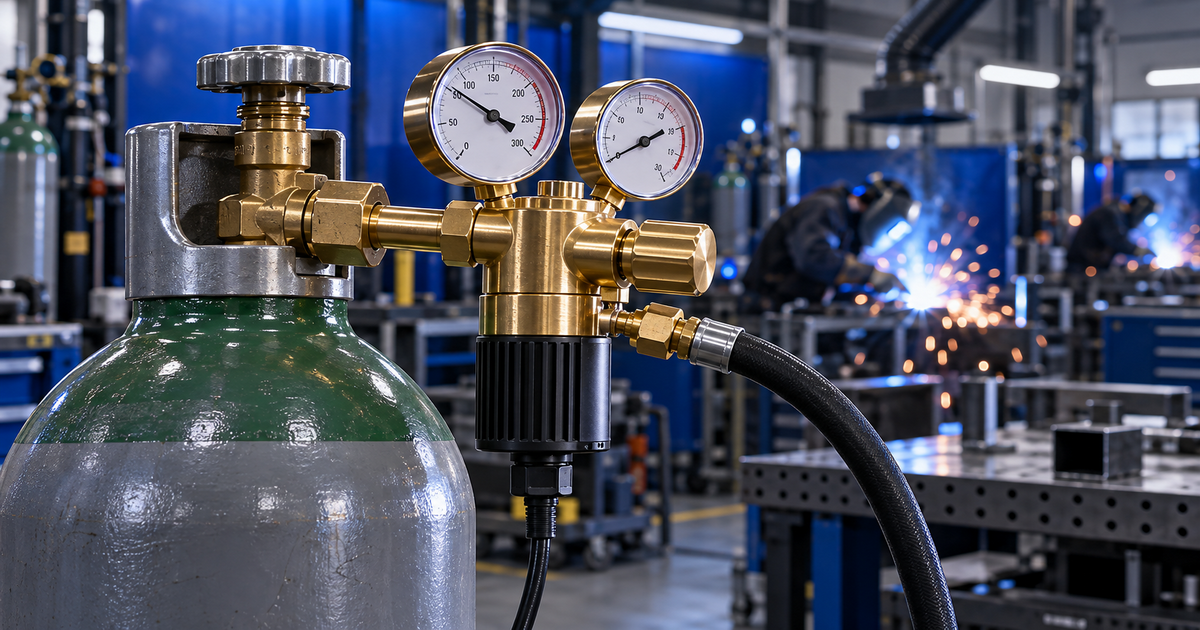
The regulator reduces high cylinder pressure to a stable delivery pressure. The flowmeter then adjusts and displays the gas flow. Both functions affect weld quality.
For aluminum production, a dual-stage argon regulator can offer an operational advantage where cylinder-pressure changes could otherwise influence the delivery pressure. A single-stage regulator may be adequate for many workshops, but dual-stage designs are often preferred where flow stability, long welding cycles, or tighter process consistency are priorities.
Choose a regulator body made from quality brass, with controlled machining, reliable threads, durable gauges, and robust seat materials. For OEM and distributor programs, consistent internal components and lot-level quality inspection matter as much as the exterior finish.
3. Cylinder connection and safety
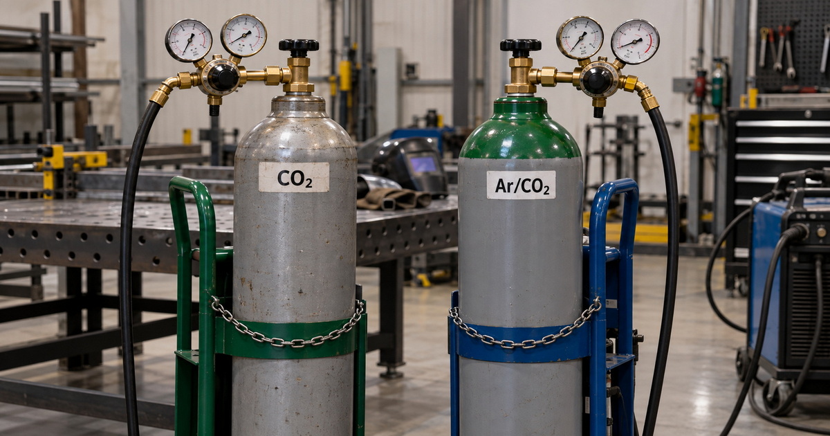
Do not force incompatible fittings. Cylinder-valve connections vary by gas and region. In North American practice, pure CO₂ cylinders commonly use a CGA-320 connection, while inert gases such as argon commonly use CGA-580.
A connection mismatch is not a minor inconvenience. It is a safety and traceability control that helps prevent the wrong regulator from being attached to the wrong gas service.
Before shipment or installation, verify:
1. The cylinder-valve standard in the destination market.
2. The gas type and gas purity.
3. The regulator inlet connection and sealing method.
4. The outlet thread, hose-barb size, or quick-connect requirement.
5. The maximum inlet pressure and working-pressure range.
6. Whether the product is for single-cylinder, manifold, or pipeline service.
4. Flow range and resolution
A meter with a 0–50 CFH range may be practical for general MIG work. However, it may offer less fine control than a lower-range meter when a TIG operator is working at modest flow rates.
For aluminum MIG, 20–30 CFH is a common starting range, although nozzle size, torch angle, drafts, joint geometry, and transfer mode can change the final setting. For TIG, the correct flow may be lower, and a gas lens, cup size, post-flow setting, and torch technique all influence the needed gas coverage.
A flowmeter should not be selected only because it reaches a high maximum flow. Resolution near the normal operating range is more useful than an oversized scale.
How to Set Argon Flow for Aluminum Welding
Start with the welding-procedure specification whenever one exists. If there is no qualified WPS, use the equipment maker’s recommendation as the initial setting, then validate it with a weld test and an outlet flow check.
Practical starting points
| Aluminum welding application | Shielding gas | Starting flow guidance | Important adjustment factors |
|---|---|---|---|
| TIG, indoor, standard cup | 100% argon | 10–20 CFH | Cup size, gas lens, tungsten extension, joint access |
| TIG, larger cup or mild air movement | 100% argon | 15–25 CFH | Drafts, torch angle, post-flow, joint geometry |
| MIG, standard aluminum work | 100% argon | 20–30 CFH | Nozzle diameter, stickout, spray/pulsed transfer, travel speed |
| MIG, thicker material or special procedure | Ar/He blend where specified | Procedure-dependent | Blend ratio, heat input, torch/nozzle, qualified WPS |
These are starting points, not universal rules. Lincoln Electric’s aluminum MIG manual lists 100% argon at 7–10 L/min under normal conditions, with adjustment up to 17 L/min when needed. This illustrates why process-specific settings and local validation are more valuable than copying a single number from a forum.
The “more gas is better” myth
Too little gas can allow oxygen, nitrogen, and moisture to reach the arc and molten aluminum. Typical symptoms include soot, porosity, dull or contaminated weld surfaces, and unstable arc behavior.
But excessive gas can create turbulence. Instead of forming a smooth shielding envelope, the high-velocity stream can draw ambient air into the coverage zone. Miller recommends using the lowest effective TIG flow rate to maintain laminar flow and reduce contamination risk.
Increase flow only after checking for leaks, drafts, damaged nozzles, incorrect torch angle, insufficient post-flow, and contaminated base material.
A Field-Test Method for Verifying Real Torch Flow
The flow indicated at the regulator is not always identical to the flow leaving the torch. Hose restrictions, leaks, damaged solenoids, long cable assemblies, and partially blocked consumables can change delivery.
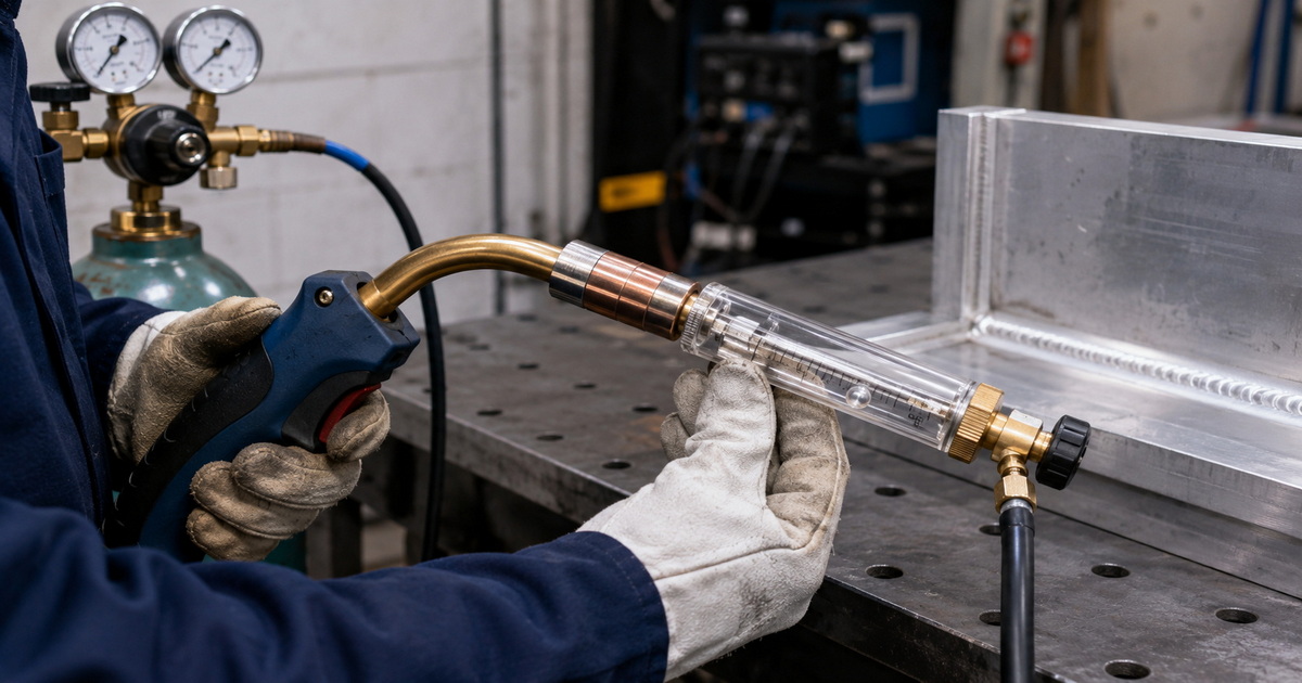
Miller recommends considering an external flowmeter at the MIG gun to monitor the CFH rate at the end of the gun.
Five-step verification process
1. Inspect the system. Check the regulator connection, hose clamps, torch cable, nozzle, diffuser, and O-rings.
2. Set an initial flow. Use the qualified procedure or a documented starting point for the welding process.
3. Measure at the outlet. Place a calibrated torch-end flow tester over the nozzle while gas is flowing.
4. Compare the readings. Record regulator-indicated flow and actual outlet flow; investigate meaningful differences.
5. Perform a weld coupon. Assess arc stability, surface cleanliness, bead appearance, and porosity under controlled conditions.
For factories supplying aluminum fabricators, this simple method can become part of incoming inspection, final assembly verification, and customer troubleshooting documentation.
Common Selection Mistakes for Distributors and OEM Buyers
Buying by appearance instead of specification
Two regulators may look nearly identical while using different seats, inlet fittings, gauge ranges, flow-tube calibrations, or gas approvals. A clear technical data sheet is more valuable than a product photo.
Using a CO₂ meter as an argon meter
A CO₂-oriented product should not be marketed as an argon solution merely because it has a flow tube. CO₂ systems also face different behavior at high withdrawal rates, including cooling concerns in some applications.
Confusing pressure with flow
A conventional pressure gauge displays pressure, not necessarily the actual volumetric gas flow at the torch. A true flowmeter helps the operator set the shielding-gas volume more directly.
Ignoring regional compliance requirements
OEM and ODM customers should define the target market before tooling and labeling are finalized. Required inlet connections, measurement units, warning labels, packaging language, and certification expectations differ by market.
How to Specify an OEM Argon Flowmeter Regulator
For distributors, welding-machine brands, and industrial-gas companies, a strong RFQ should include more than “argon regulator with flowmeter.”
Specify the following:
– Gas service: Pure argon, argon/helium, or approved argon mixtures.
– Application: TIG, MIG, robotic welding, manual welding, purging, or laboratory use.
– Flow range and units: CFH, L/min, or dual-scale requirements.
– Accuracy requirement: State the accepted tolerance and test conditions.
– Inlet standard: Confirm the cylinder connection for the sales market.
– Outlet configuration: Hose barb, thread, quick connector, or dual outlet.
– Regulator architecture: Single-stage or dual-stage.
– Body material: High-quality brass is common for durability and corrosion resistance.
– Branding: Logo, dial artwork, package design, barcode, and multilingual manual.
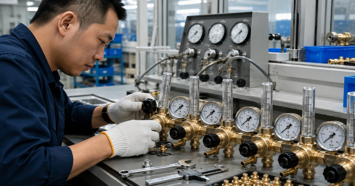
– Quality plan: Pressure test, leak test, flow verification, visual inspection, and batch traceability.
A professional manufacturer should be able to convert this information into a controlled drawing, sample-approval process, inspection standard, and repeatable production plan.
Final Recommendation
For aluminum welding, select an argon flow meter regulator, not just any welding gas flow meter. The product must be rated for the actual gas, fitted to the correct cylinder valve, scaled for argon flow, and sized for the process’s normal operating range.
For private-label and industrial customers, the most reliable path is to source a precision brass argon regulator with stable pressure control, defined flow accuracy, documented quality inspection, and OEM/ODM customization matched to the destination market. Contact our engineering team to discuss your required gas type, connection standard, flow range, branding, and quality-control requirements.
FAQ
1. Can I use a CO₂ welding regulator for argon?
Only if the manufacturer explicitly states that the exact regulator and flowmeter are approved, correctly calibrated, and fitted for argon service. In practice, aluminum welding buyers should select an argon-specific model with the appropriate inert-gas connection and flow scale.
2. What gas flow should I use for MIG welding aluminum?
A common starting point is 20–30 CFH with 100% argon, but the correct final value depends on the nozzle, transfer mode, torch angle, base-metal condition, and airflow around the weld area.
3. Why does my aluminum weld have black soot or porosity?
Possible causes include inadequate or turbulent shielding gas, leaks, drafts, a blocked nozzle, excess torch angle, poor cleaning, moisture, or contamination. Verify actual flow at the torch before increasing the regulator setting.
4. Is a dual-stage argon regulator worth the extra cost?
For high-volume production, long welding cycles, or applications demanding greater delivery-pressure stability as cylinder pressure falls, a dual-stage regulator can be a sound investment. For basic intermittent work, a quality single-stage argon flowmeter regulator may be sufficient.
5. Can I use one flowmeter for argon and argon/helium blends?
Only use it if the manufacturer provides a correct scale, conversion method, or explicit approval for that gas blend. Helium’s different physical properties can require different flow settings and calibration considerations.
6. Should I choose CFH or L/min?
Choose the unit your target customers use most often. CFH is common in the United States, while L/min is widely used in many international markets. Dual-scale models can simplify global distribution.
7. How often should an argon flowmeter regulator be inspected?
Inspect it before use for leaks, damaged gauges, cracked flow tubes, blocked outlets, and worn seals. Establish calibration or verification intervals based on your quality system, process criticality, operating frequency, and local customer requirements.
References
1. [Miller Electric — How to Successfully MIG Weld Aluminum] — Aluminum shielding-gas and recommended MIG flow-rate guidance. [millerwelds]
2. [Miller Electric — Best Practices for Proper Shielding Gas in TIG Welding] — TIG argon guidance, typical flow range, and lowest-effective-flow principle. [millerwelds]
3. [Miller Electric — What Type of Gas Is Best for MIG Welding?] — Argon use for aluminum and torch-end flowmeter recommendation. [millerwelds]
4. [Lincoln Electric — REDI-MIG 455 Operator Manual] — Aluminum MIG parameter guidance using 100% argon. [assets.lincolnelectric]
5. [American Welding Society Forum — Flow Meter or Regulator] — Practical explanation of gas-specific flowmeter scales and flowmeter accuracy. [app.aws]
6. [YesWelder — How to Set Gas Pressure for MIG Welding] — General connection and gas-flow context; validate equipment compatibility independently. [yeswelder]
Hot Tags: Argon Flow Meter Regulator, Welding Gas Flow Meter, Aluminum Welding Gas Regulator, Argon Regulator Manufacturer, TIG Welding Argon Flow Meter, MIG Welding Gas Regulator, Dual Stage Argon Regulator, OEM Gas Regulator Supplier, Industrial Gas Flow Meter, Brass Welding Gas Regulator