Content Menu
● How a Dual Output Argon Regulator Works
>> Dual Output Does Not Mean Dual Stage
● Why TIG Welding and Back Purging Need Separate Control
>> Torch Shielding Requires Controlled Coverage
>> Back Purging Requires Atmosphere Control
● Argon Flow Rates: Useful Starting Points, Not Universal Settings
● Selecting a Dual Flowmeter Argon Regulator
>> Confirm Inlet Compatibility and Pressure Rating
>> Match Flow Ranges to the Application
>> Evaluate Materials, Assembly, and Documentation
● A Practical Setup Procedure for TIG Welding and Back Purging
● Test Both Outlets Under Simultaneous Demand
● Reduce Purge Volume Before Increasing Flow
● Specify Oxygen Acceptance Separately from Flow
● Troubleshooting Common Dual Output Regulator Problems
● Safety: Argon Is Inert, but It Can Displace Oxygen
● OEM and ODM Requirements for Overseas Buyers
● Specify Your Dual Output Argon Regulator
>> 1.Can one argon cylinder supply TIG welding and back purging?
>> 2.Is a dual output regulator the same as a dual-stage regulator?
>> 3.Can I replace a dual flowmeter regulator with a simple splitter?
>> 4.What argon flow rate should I use for TIG welding?
>> 5.Do all stainless steel welds require the same purge oxygen level?
>> 6.Can both outlets supply different gases?
A dual output argon regulator for TIG welding and back purging supplies two separately controlled gas lines from one argon cylinder. One line shields the tungsten and weld pool; the other protects the underside of the joint. For stainless steel fabricators, pipework contractors, and equipment distributors, this arrangement simplifies gas delivery while allowing different flow settings for each task.
However, two outlets alone do not guarantee effective shielding. Regulator capacity, flowmeter calibration, hose layout, purge containment, and operator technique all influence performance. From a manufacturing and procurement perspective, the right question is not simply, “Does it have two outlets?” It is, “Can it supply both circuits consistently under actual working conditions?”
How a Dual Output Argon Regulator Works
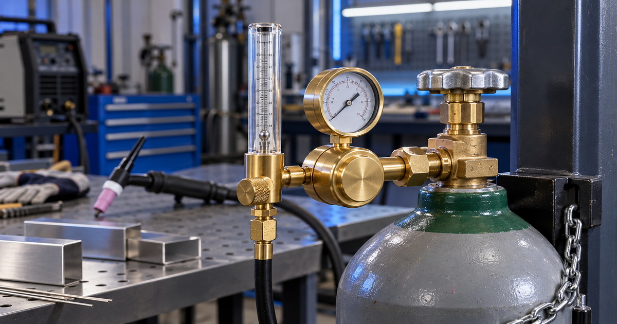
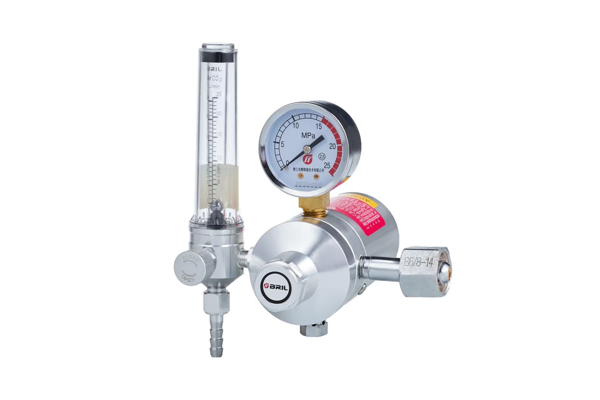
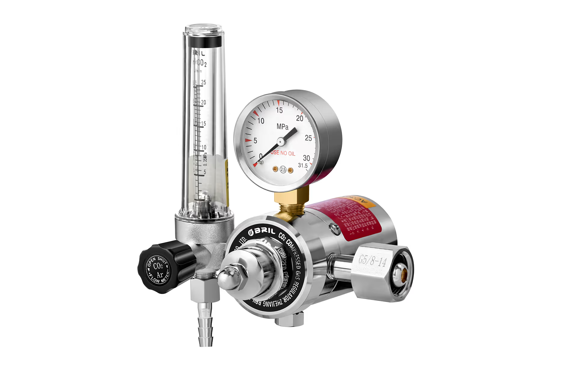
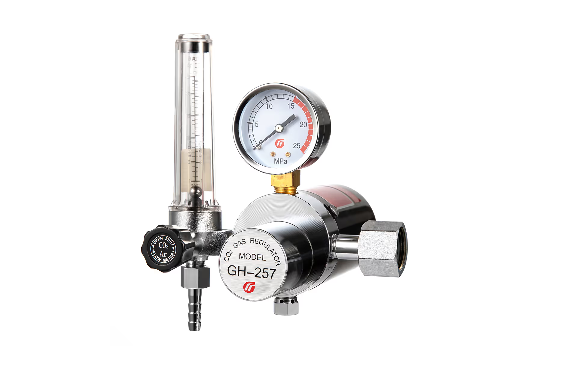
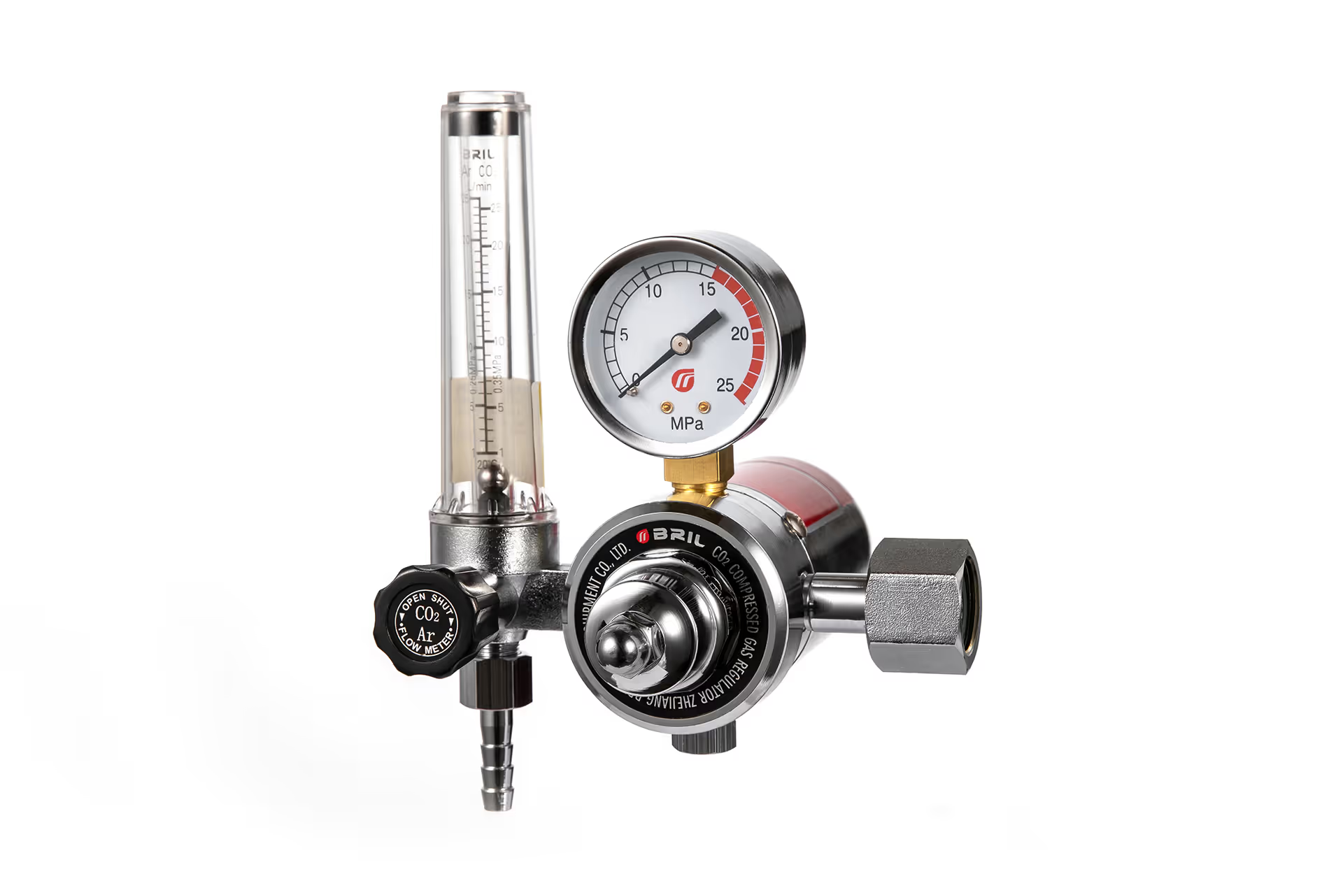
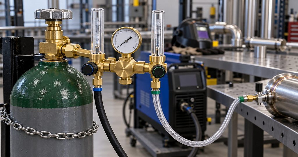
A typical dual flowmeter argon regulator combines a cylinder connection, pressure-reducing mechanism, cylinder-pressure gauge, and two adjustable flowmeter outlets.
The regulator reduces cylinder pressure to a suitable working pressure. Each downstream flow control then meters gas to its connected circuit.
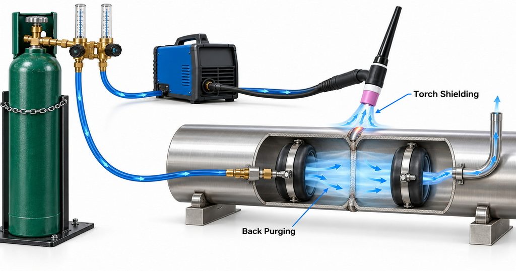
For TIG welding and back purging, the usual arrangement is:
– Outlet one supplies the welding machine’s gas inlet or a compatible torch arrangement.
– Outlet two supplies a purge hose connected to a pipe, chamber, or localized purge enclosure.
Commercial dual flowmeter regulators demonstrate this configuration: two independently adjustable flows supplied from one common gas source.
Dual Output Does Not Mean Dual Stage
These terms describe different features.
| Term | What it describes | Practical significance |
|---|---|---|
| Dual output | Two gas delivery outlets | Supports two downstream circuits |
| Dual flowmeter | Two flow-measuring channels | Allows separate flow adjustment and indication |
| Dual stage | Two pressure-reduction stages | Helps limit delivery-pressure changes as cylinder pressure falls |
| Dual gauge | Two pressure gauges | Does not necessarily provide two outlets or measured flows |
A dual output regulator may be single-stage or dual-stage. Buyers should confirm the actual pressure-control architecture rather than infer it from the number of gauges or flow tubes.
Why TIG Welding and Back Purging Need Separate Control
Torch shielding and root protection solve different problems.
At the torch, argon protects the tungsten, molten weld pool, and nearby hot metal from atmospheric contamination. Inside a pipe or behind a joint, purge gas displaces air to protect the weld root.
Torch Shielding Requires Controlled Coverage
Insufficient shielding can contribute to oxidation, porosity, and tungsten contamination. Excessive flow can also cause problems by creating turbulence that draws surrounding air into the shielding stream.
More gas is therefore not automatically better. Cup size, gas-lens arrangement, electrode extension, drafts, and the welding procedure all affect the required setting.
Back Purging Requires Atmosphere Control
Back purging is not simply a second torch application. Its purpose is to establish and maintain an acceptable atmosphere behind the joint.
For stainless steel work, inadequate root protection can produce heavy oxidation, often called sugaring. Where internal cleanliness and corrosion performance matter, root condition becomes a significant quality concern.
The practical objective is to control residual oxygen—not merely to achieve a particular flowmeter reading.
Argon Flow Rates: Useful Starting Points, Not Universal Settings
Miller identifies approximately 15–20 cubic feet per hour as a troubleshooting starting point for TIG shielding, while its broader guidance describes a typical range of 10–35 CFH depending on consumables and conditions.
The narrower range equals approximately 7–9.5 liters per minute. These figures are reference points, not substitutes for a qualified welding procedure specification, or WPS.
| Circuit or operating phase | Main objective | What determines the setting |
|---|---|---|
| TIG torch shielding | Protect the tungsten and weld pool | Cup, gas lens, extension, drafts, and procedure |
| Initial pre-purge | Displace air from the enclosed volume | Volume, geometry, leakage, and venting |
| Purge during welding | Maintain the required atmosphere | Oxygen readings, sealing, and joint conditions |
| Post-weld protection | Protect hot material during cooling | Alloy, procedure, and acceptance requirements |
A purge circuit may require one setting during initial displacement and another during welding. Do not automatically copy the torch flow setting onto the purge outlet.
Selecting a Dual Flowmeter Argon Regulator
Confirm Inlet Compatibility and Pressure Rating
The cylinder connection must match the destination market, cylinder valve, gas service, and applicable requirements.
For example, CGA-580 connections appear on commercial argon regulators intended for compatible North American cylinders. That does not make them suitable for every country or installation.
Specify:
– Cylinder connection designation.
– Maximum rated inlet pressure.
– Intended gas service.
– Outlet thread and hose connection.
– Required operating orientation.
Avoid treating adapters as a substitute for selecting the correct regulator assembly.
Match Flow Ranges to the Application
An oversized flow scale can make small adjustments difficult to distinguish. Conversely, a low-capacity unit may not support simultaneous torch flow and initial purge demand.
Review both individual outlet ranges and total regulator capacity. Ask whether published performance applies with both outlets flowing.
Also confirm that the flowmeter is calibrated for argon and the specified operating pressure. A scale intended for another gas or pressure condition may not indicate the actual argon flow correctly.
Evaluate Materials, Assembly, and Documentation
Brass bodies are widely used in commercial welding regulators, but material description alone does not establish reliability.
Precision machining, sealing surfaces, seat design, assembly cleanliness, and inspection all matter.
For procurement, request model-specific documentation covering pressure ratings, flow ranges, connection dimensions, operating instructions, and inspection criteria. A general statement about “international standards” should never replace identifiable conformity evidence for the supplied model.
A Practical Setup Procedure for TIG Welding and Back Purging
Always follow the regulator, cylinder supplier, welding equipment, and workplace instructions. The following sequence supports planning; it does not replace operator training.
1. Secure the cylinder upright and inspect the equipment for damage.
2. Confirm the regulator’s gas compatibility, inlet connection, and pressure rating.
3. Connect the regulator using the manufacturer’s prescribed installation method.
4. Connect one outlet to the welding gas circuit and the other to the purge assembly.
5. Prepare a localized purge enclosure where practical.
6. Provide a controlled vent path so displaced air can escape.
7. Open the cylinder and pressurize the assembly according to the equipment instructions.
8. Check connections using an approved leak-detection method.
9. Set torch flow while gas is actually flowing through the torch circuit.
10. Establish the purge atmosphere and verify the required oxygen level.
11. Recheck performance with both circuits operating.
12. Maintain shielding and purge protection for the duration required by the procedure.
Never use a flame for leak checking. Never seal a purge enclosure without an appropriate vent path.
Test Both Outlets Under Simultaneous Demand
Separately adjustable outlets are useful, but they still share an upstream gas supply. Changing demand on one branch can expose limitations in regulator capacity or system configuration.
A meaningful commissioning check should reproduce actual use:
– Establish purge flow.
– Activate the torch gas circuit.
– Observe whether the indicated purge flow changes.
– Adjust the purge circuit and check torch delivery again.
– Repeat within the equipment’s approved operating conditions.
For a manufacturer or distributor, this is a more useful acceptance discussion than asking only whether both needle valves operate smoothly.
Where repeatability matters, agree on the test conditions and acceptance limits before placing the order. Do not assume every dual outlet regulator delivers identical simultaneous-flow performance.
Reduce Purge Volume Before Increasing Flow
One of the most useful gas-saving opportunities is the volume being purged.
Purging a long pipe section consumes more gas than protecting a short, properly isolated zone around the joint. Suitable purge dams or other containment systems can reduce the volume that must be displaced.
Consider a simplified example:
– Enclosed volume: 12 liters.
– Selected pre-purge flow: 6 liters per minute.
– One nominal volume replacement: 2 minutes.
That calculation describes gas delivery only. It does not prove that the atmosphere is ready for welding. Mixing, trapped air, leakage, and joint geometry prevent a simple time calculation from guaranteeing a specific oxygen level.
Use volume calculations for planning. Use an appropriate oxygen measurement and the welding procedure for acceptance.
Specify Oxygen Acceptance Separately from Flow
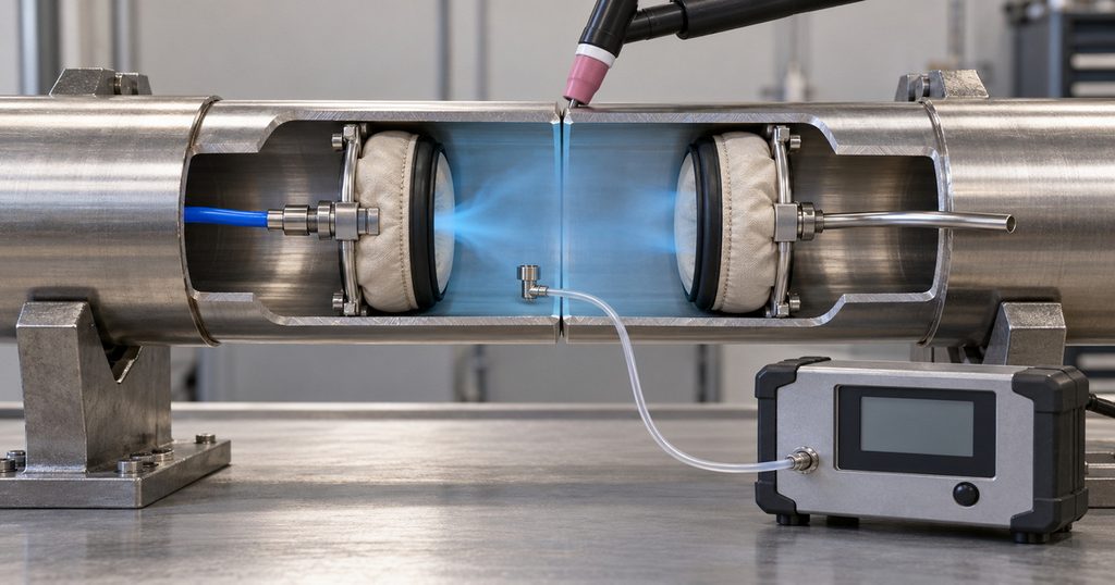
A flowmeter measures gas delivery. A purge monitor measures oxygen concentration. These instruments answer different questions.
Purge-monitor manufacturers discuss measurement around 100 ppm for stainless steel applications and lower levels for certain reactive or demanding alloys. Such guidance illustrates the need for sensitive monitoring, but it does not establish a universal acceptance threshold.
The project specification or qualified procedure should define:
– Maximum acceptable oxygen concentration.
– Sampling location.
– Instrument measurement capability.
– Whether monitoring must continue during welding.
– Required protection during cooling.
Avoid using weld color alone as proof of adequate purge control. For demanding work, record the atmosphere conditions alongside the relevant welding parameters.
Troubleshooting Common Dual Output Regulator Problems
| Symptom | Possible causes | Practical checks |
|---|---|---|
| Dark or heavily oxidized root | Air leakage, incomplete purge, inadequate protection duration | Check seals, sampling location, and oxygen readings |
| Porosity despite high torch flow | Turbulence, leaks, drafts, contamination | Check the complete shielding circuit |
| Purge indication changes when torch gas starts | Shared supply limitations or system interaction | Test simultaneous demand and confirm capacity |
| Unstable flow indication | Incorrect orientation, contamination, pressure mismatch | Follow installation and service instructions |
| High argon consumption | Excessive settings, leaks, unnecessarily large purge volume | Check leakage and containment before increasing flow |
Do not dismantle pressure equipment beyond the maintenance permitted by its manufacturer. Remove damaged or malfunctioning equipment from service and arrange qualified evaluation.
Safety: Argon Is Inert, but It Can Displace Oxygen
Argon does not need to burn or react chemically to create a serious hazard. It can displace oxygen and cause suffocation, particularly in enclosed or confined spaces.
Purge exhaust therefore requires deliberate management. Never assume that a gas suitable for welding is safe to breathe.
Essential precautions include:
– Secure cylinders against falling.
– Protect hoses from heat, sharp edges, and mechanical damage.
– Provide appropriate ventilation.
– Evaluate oxygen-deficiency risks.
– Follow confined-space procedures where applicable.
– Use equipment only for its designated gas service.
An argon regulator should not be reassigned to oxygen, acetylene, or propane simply because a connection appears adaptable.
OEM and ODM Requirements for Overseas Buyers
For overseas brands, wholesalers, distributors, and equipment manufacturers, customization should start with a defined application—not only a logo or packaging design.
Our manufacturing focus includes precision production, brass components, quality inspection, and customized gas-control solutions. For a dual output argon regulator project, those priorities should become clear, verifiable purchasing requirements.
A useful enquiry should include:
– Destination market and cylinder connection.
– Maximum cylinder pressure.
– Required flow range for each outlet.
– Expected simultaneous gas demand.
– Preferred units: L/min, CFH, or a specified dual scale.
– Hose connections and installation arrangement.
– Branding, packaging, and instruction-language requirements.
– Applicable conformity and inspection documentation.
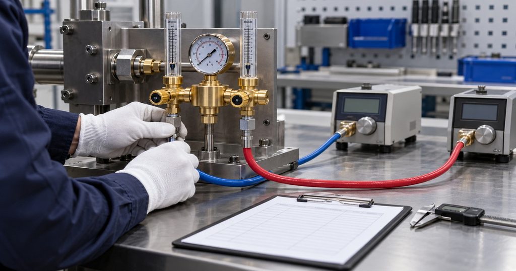
Before volume production, evaluate samples in a representative welding and purge setup. Confirm readability, adjustment behavior, connection compatibility, and simultaneous-flow performance.
Specify Your Dual Output Argon Regulator
Send us your destination market, cylinder connection, inlet pressure, required outlet flow ranges, and TIG/back-purging application. Our team can review OEM or ODM requirements and help define a configuration for sample evaluation before production.
Frequently Asked Questions
1.Can one argon cylinder supply TIG welding and back purging?
Yes. A suitable dual output regulator can supply both circuits, provided its total capacity, individual flow ranges, and connections match the application.
2.Is a dual output regulator the same as a dual-stage regulator?
No. Dual output describes two delivery outlets. Dual-stage describes two pressure-reduction stages. A product can have either feature independently.
3.Can I replace a dual flowmeter regulator with a simple splitter?
A splitter creates additional branches but does not, by itself, provide separate flow measurement and control. Any alternative arrangement must include suitable downstream controls and verified capacity.
4.What argon flow rate should I use for TIG welding?
Approximately 15–20 CFH is one published starting range, but the correct setting depends on the torch configuration, environment, and welding procedure. Excessive flow can reduce shielding effectiveness.
5.Do all stainless steel welds require the same purge oxygen level?
No. Requirements vary with the alloy, service conditions, joint design, and acceptance specification. Use the applicable procedure rather than a universal ppm target.
6.Can both outlets supply different gases?
Not from a single-cylinder dual output regulator. Both outlets receive gas from the same source. Different gases require an appropriately designed supply system.
References
1. Miller Electric, “Common TIG Welding Problems.” Guidance on shielding-gas settings, turbulence, leaks, and contamination. [millerwelds]
2. Miller Electric, “Best Practices for Proper Shielding Gas in TIG Welding.” Discussion of flow ranges, shielding behavior, and flow measurement. [millerwelds]
3. Airgas, “Harris Model 356 DUAL Dual Heavy Duty Argon/Helium Flowmeter Regulator.” Commercial example of two separately adjustable flows from one source. [airgas]
4. Huntingdon Fusion Techniques, “Pipe Purging Accurately Down to 10 ppm.” Manufacturer guidance on purge monitoring for stainless steel and reactive alloys. [huntingdonfusion]
5. Airgas, “Harris Model 355-2-Ar/He-580 Flowmeter Regulator.” Example specifications covering brass construction, calibration, connections, and mounting orientation. [airgas]
6. Oregon OSHA, “Compressed Gas Safety.” Guidance on compressed-gas hazards, training, oxygen displacement, and asphyxiation. [osha.oregon]
7. OSHA, “Controlling Hazardous Fume and Gases during Welding.” Guidance on argon-related oxygen displacement and enclosed-space hazards. [osha]
Hot Tags: Dual Output Argon Regulator, Dual Flowmeter Argon Regulator, Argon Regulator for TIG Welding, Argon Regulator for Back Purging, Argon Regulator Manufacturer, Argon Regulator Supplier, Wholesale Argon Regulators, OEM Argon Regulator, ODM Argon Regulator, Industrial Argon Gas Regulator